
Status: AVAILABLE
Guided Mode is intended for anyone who has never milled before. The application asks simple questions and handles the technical decisions. Start it with the Guided Mode button at the top, ⇧⌘G, or Prefer guided in the setup assistant.
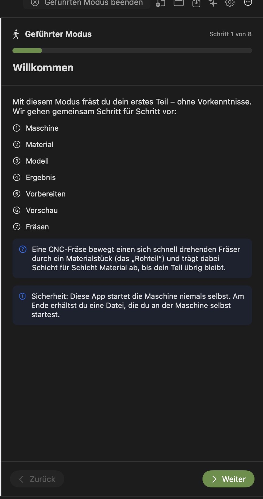
On the right you see “Step n of 8”, a progress bar, and Back and Next. The 3D workspace remains visible.
Step 1: Welcome
A short explanation of what a CNC mill does, how the workflow works, and that the application never starts the machine itself.
Step 2: Machine
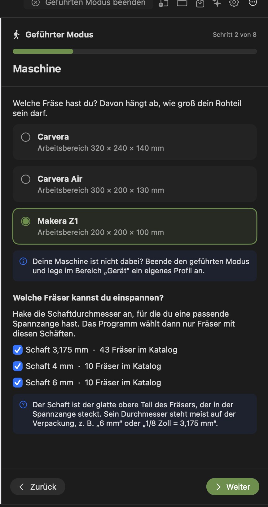
“Which mill do you have?” — the choices are:
| Machine | Working envelope |
|---|---|
| Carvera | 320 × 240 × 140 mm |
| Carvera Air | 300 × 200 × 130 mm |
| Makera Z1 | 200 × 200 × 100 mm |
If your machine is not listed, exit Guided Mode and create a custom profile in Device.
Below, answer “Which cutters can you clamp?”: tick the shank diameters for which you have a matching collet — e.g. 3.175 mm shank (43 cutters in the catalog), 4 mm shank (10 cutters) and 6 mm shank (10 cutters). The application then plans only with cutters you can actually clamp. A tip from the app: the shank diameter is usually printed on the packaging, e.g. “6 mm” or “1/8 inch = 3.175 mm”.
Step 3: Material
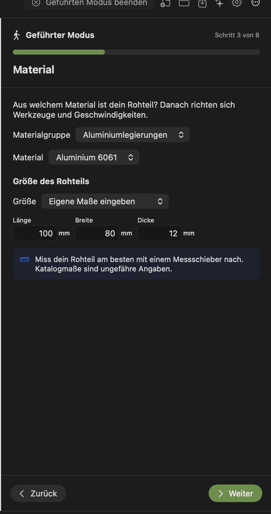
“What material is your stock made of?” — material group, material and stock size (length, width, thickness), as in the setup assistant. The notice reminds you: “It is best to measure your stock with calipers.”
Step 4: Model
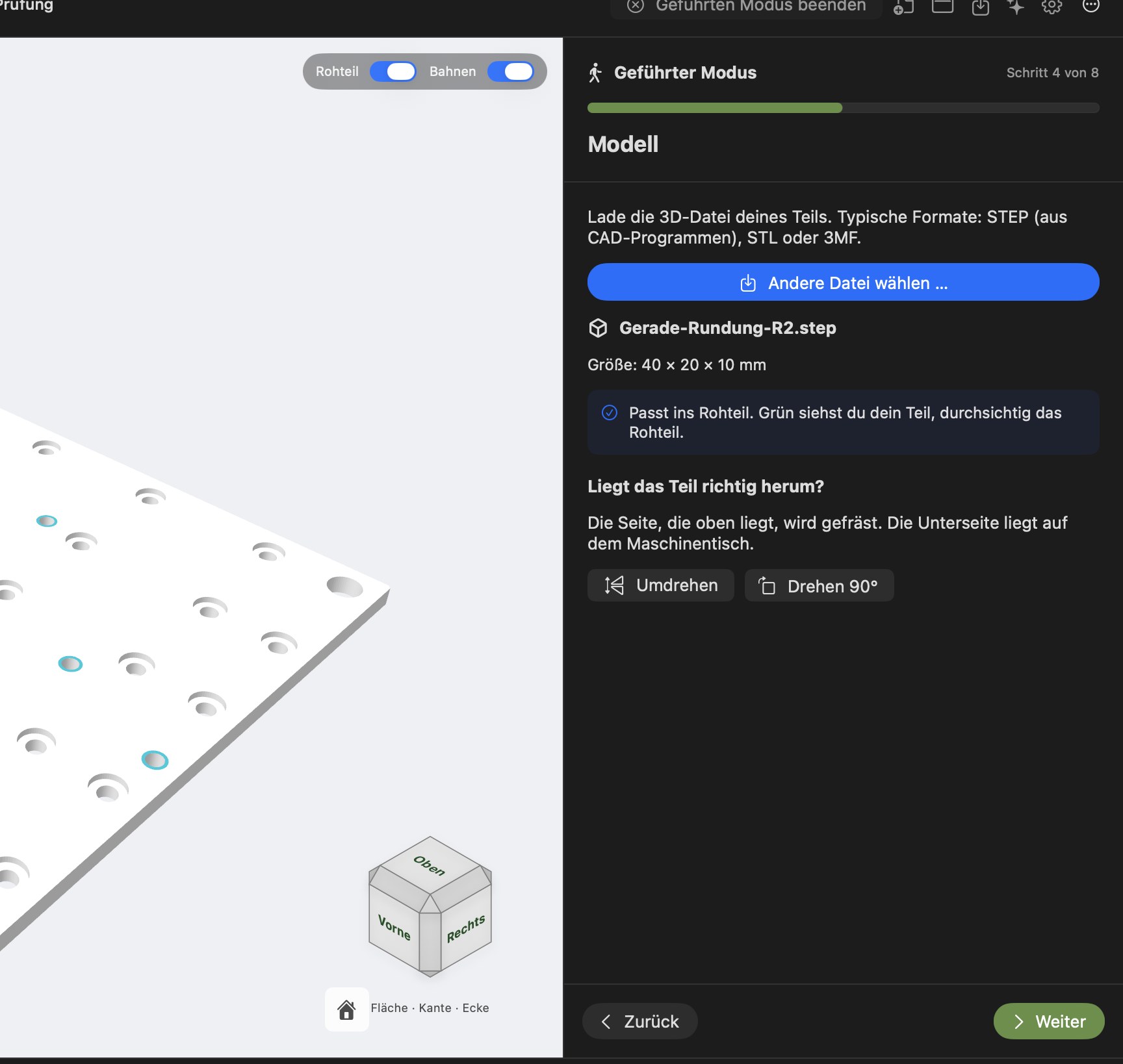
Use Select File … to load a 3D model (STEP from CAD applications, STL or 3MF) or a 2D drawing (DXF or SVG). For a model, the application shows the file name, the size, and whether the part fits in the stock (“Your part is shown in green; the stock is transparent”).
2D drawing (DXF/SVG): The drawing is centred on the top face of the stock and shown in blue. The app shows its size and the number of closed shapes and open lines, and warns if the drawing is larger than the stock. Status: EXPERIMENTAL — checked computationally and virtually.
For a 3D model, under “Is the part the right way up?”, remember: the top side will be milled; the underside rests on the machine table. Use Flip and Rotate 90° to orient the part correctly.
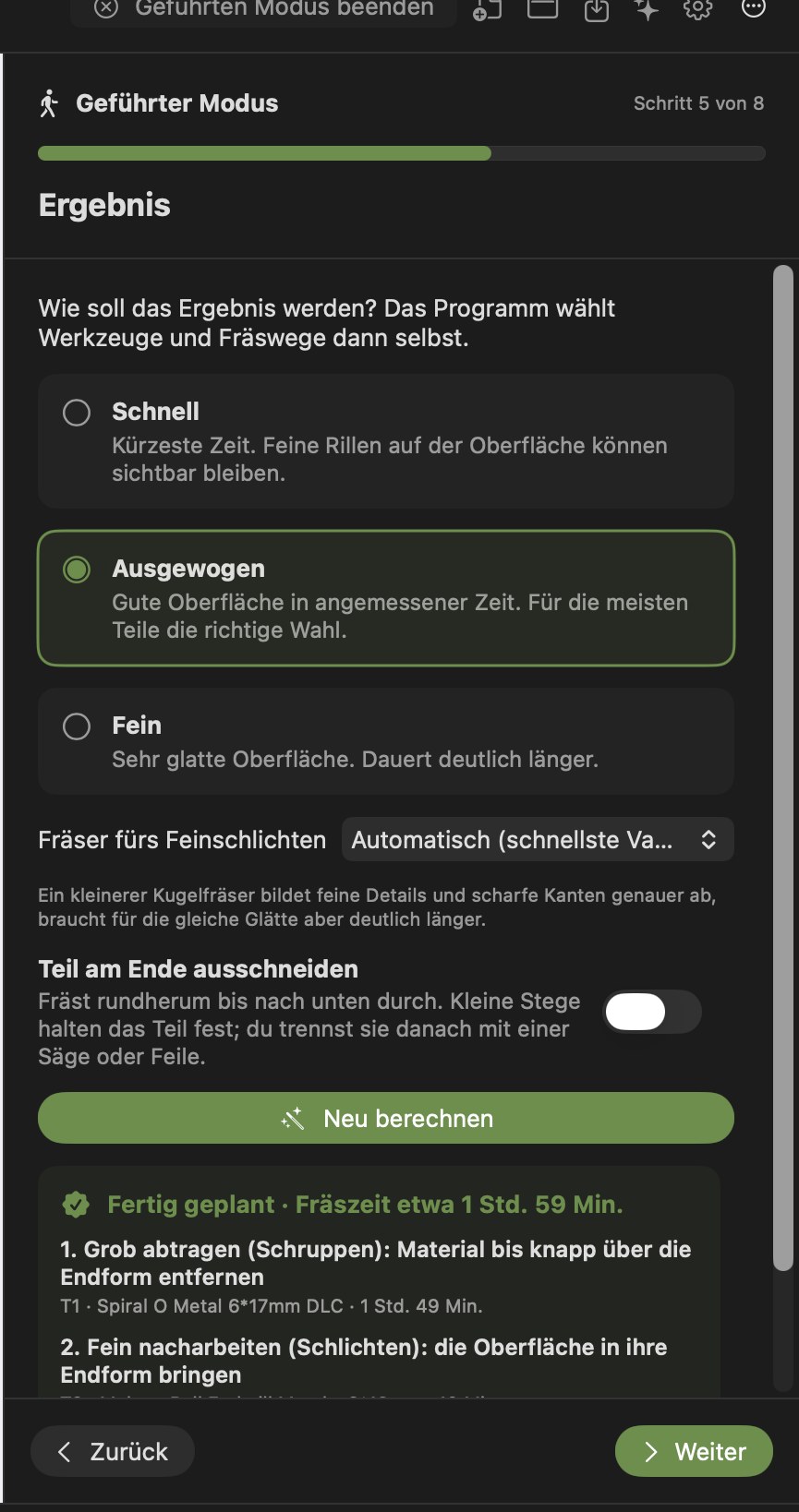
Step 5: Result
For a 3D model, choose the desired quality:
- Fast — shortest time; fine grooves may remain visible.
- Balanced — a good surface in a reasonable time (right for most parts).
- Fine — a very smooth surface; takes considerably longer.
Optional:
- Cut out the part at the end — mills all the way around and through to the bottom; four small tabs hold the part in place.
- Fine-finishing cutter — “Automatic” (fastest variant) or a specific ball size.
For a 2D drawing, choose what to do:
- Cut out — mills closed shapes through the stock, starting with inner holes and then the outer profile with four small holding tabs. Put a spoilboard underneath.
- Recess (pockets) — clears the area inside closed shapes to the selected depth and leaves inner shapes as islands. Internal corners retain the cutter radius.
- Engrave lines — follows the centre of all lines, including open ones such as lettering. A depth of 0.3 to 1 mm is often sufficient. The cutter diameter determines the line width.
The app compares up to three cutter sizes from the catalog and selects the fastest fully calculated option. For engraving it uses the finest cutter. Cut-out and recess ignore open lines and report this in the result.
Work zero at the machine — before calculating, choose where to set X, Y and Z on the machine: Bottom · Centre, Top · Centre, or Top · Front-left corner. A plain-language description appears below the choice. “Top” sets Z at the stock surface, while “Bottom” sets Z at the supporting face, which can suit cut-out jobs. Changing the zero requires recalculation.
With Calculate Plan, the application creates the complete plan: roughing with the largest suitable flat end mill, finishing with a ball-nose cutter, and optionally cutting out with a ramp and tabs. If the project already has operations, they are replaced (Undo remains available). Calculation runs in the background and can be cancelled.
Afterwards, for example, “Planning complete · Milling time approximately 1 hr 59 min” appears with the individual steps in plain language:
- Remove bulk material (roughing): remove material to just above the final shape — e.g. T1 · 6 mm flat end mill.
- If needed: Remove remaining material (rest roughing) with a smaller cutter where the larger one could not reach — e.g. T3 · 4 mm flat end mill.
- Refine the surface (finishing): bring the surface to its final shape — e.g. T2 · 4 mm ball-nose cutter.
- Optional: Cut out with tabs.
Step 6: Prepare
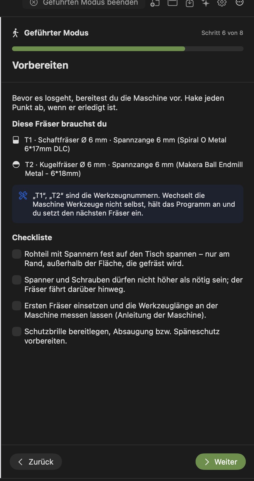
“These are the cutters you need”: a list with tool number (T1, T2 …), type, diameter, matching collet and catalog name. The app explains: “T1” and “T2” are tool numbers — if the machine does not change tools automatically, the program stops and you insert the next cutter.
There is also a checklist to tick off:
- Clamp the stock firmly to the table — only at the edges, outside the area to be milled.
- Clamps and screws should be no higher than necessary; the cutter travels over them.
- Insert the first cutter and have its tool length measured at the machine.
- Have safety glasses ready and prepare extraction or chip protection.
- When cutting out: place a spoilboard underneath.
Step 7: Preview
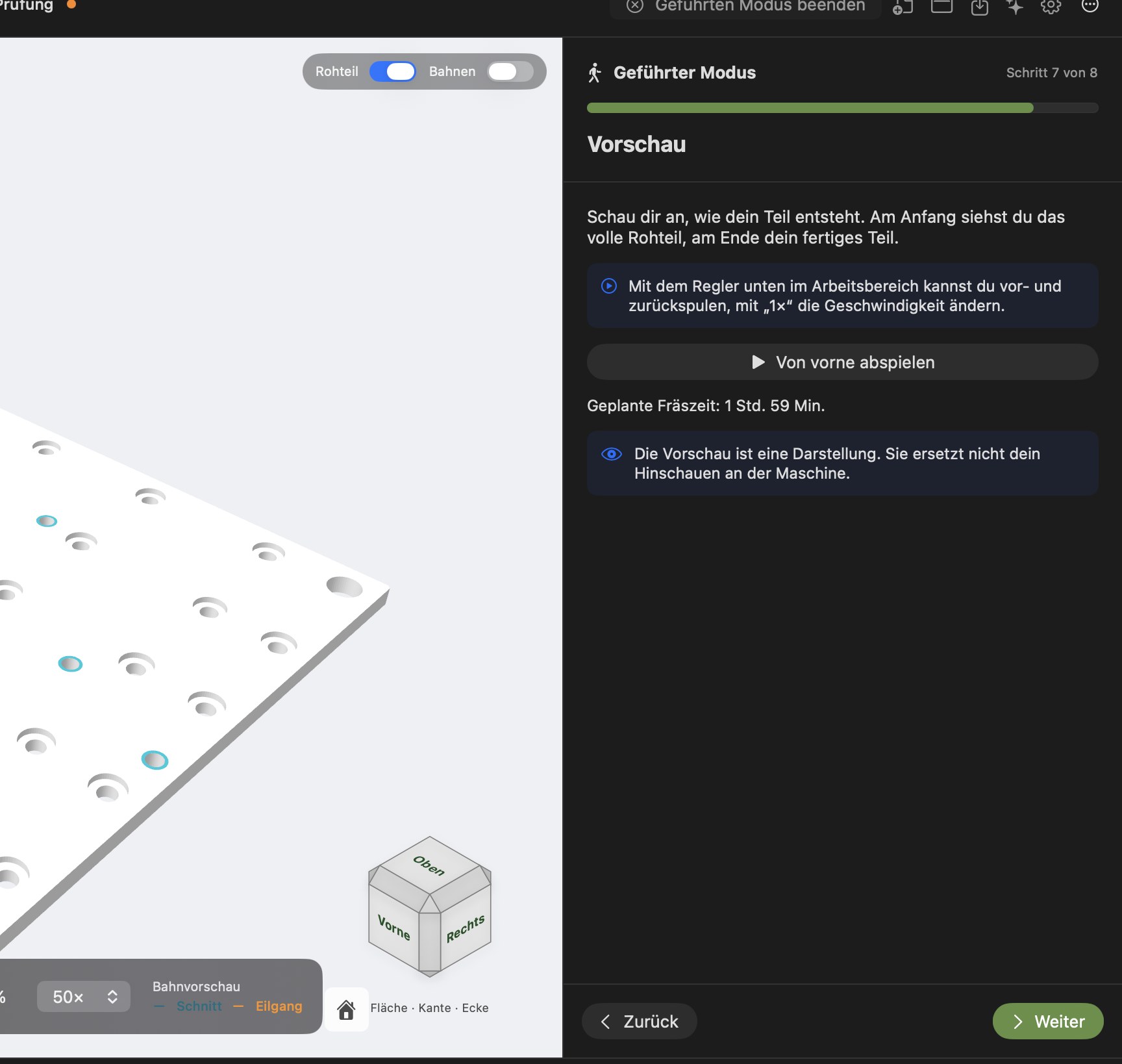
The live preview starts automatically: at the beginning you see the full stock; at the end, your finished part. Use the slider at the bottom to move backwards and forwards, and “1×” through “50×” to change playback speed. Play from the beginning restarts it. The planned milling time is shown. A notice in the app says: “The preview is a visualization. It does not replace watching what happens at the machine.”
Step 8: Mill
- Create File for the Machine … — opens export control and generates the machine file. For Makera Z1, Guided Mode uses the “Makera Z1 Pro · XYZ” planning profile, which is maintained by 645DF and has no manufacturer approval, and generates Z1 files, one per machining step. These files contain no automatic tool change or homing cycle. Other machines without a dedicated format receive a checked NC draft. Confirm all four setup conditions again for the Z1 export. Check the tool, stock, workholding and work zero. The window describes the work zero in plain language.
- Save Project.
- At the machine: transfer the file (USB stick, Wi-Fi or cable — see your machine’s instructions), set the zero point as described in the export window, press Start at the machine and watch attentively for the first few minutes (use Stop/Emergency Stop immediately if a problem occurs), then separate the tabs and deburr the edges.
“The app does not transfer anything automatically and never starts the machine.”
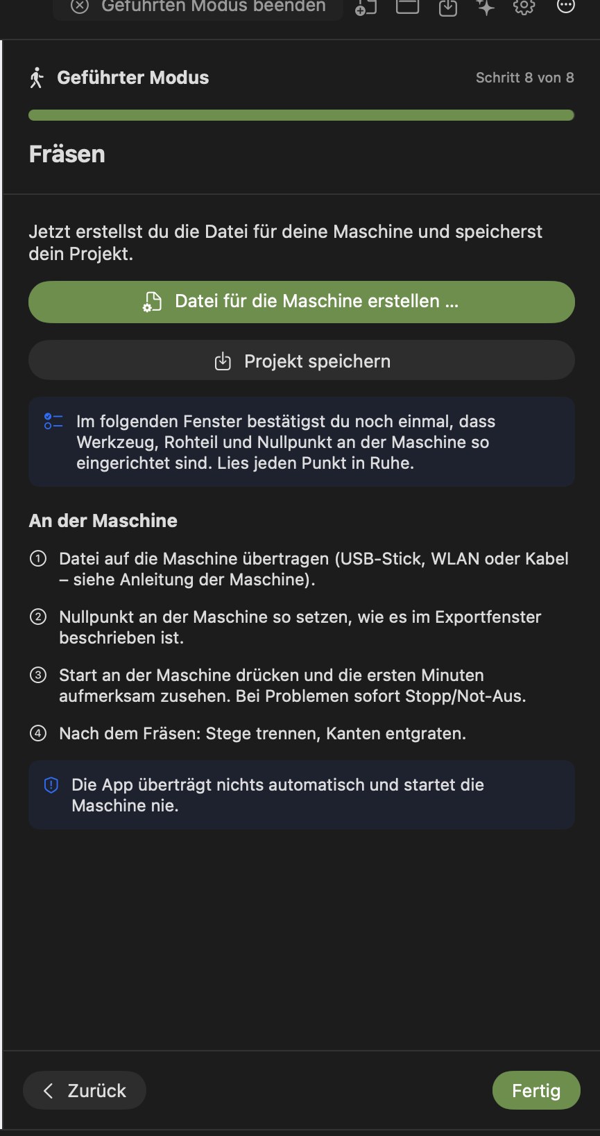
Use Done or Exit Guided Mode to return to the normal view. Everything Guided Mode planned can be adjusted further there.
Limits of Guided Mode: rectangular stock, machining from above, one part or one drawing. The app can use catalog values for materials such as ABS, acrylic (PMMA), POM, polycarbonate, printed circuit board material (FR4), MDF and CFRP. Catalog values are unavailable for Bakelite, epoxy and engineered stone. Cutting parameters are taken unchanged from the catalog and are deliberately conservative — milling times can therefore be long. Custom cutting parameters are available in expert mode.