
Status: AVAILABLE
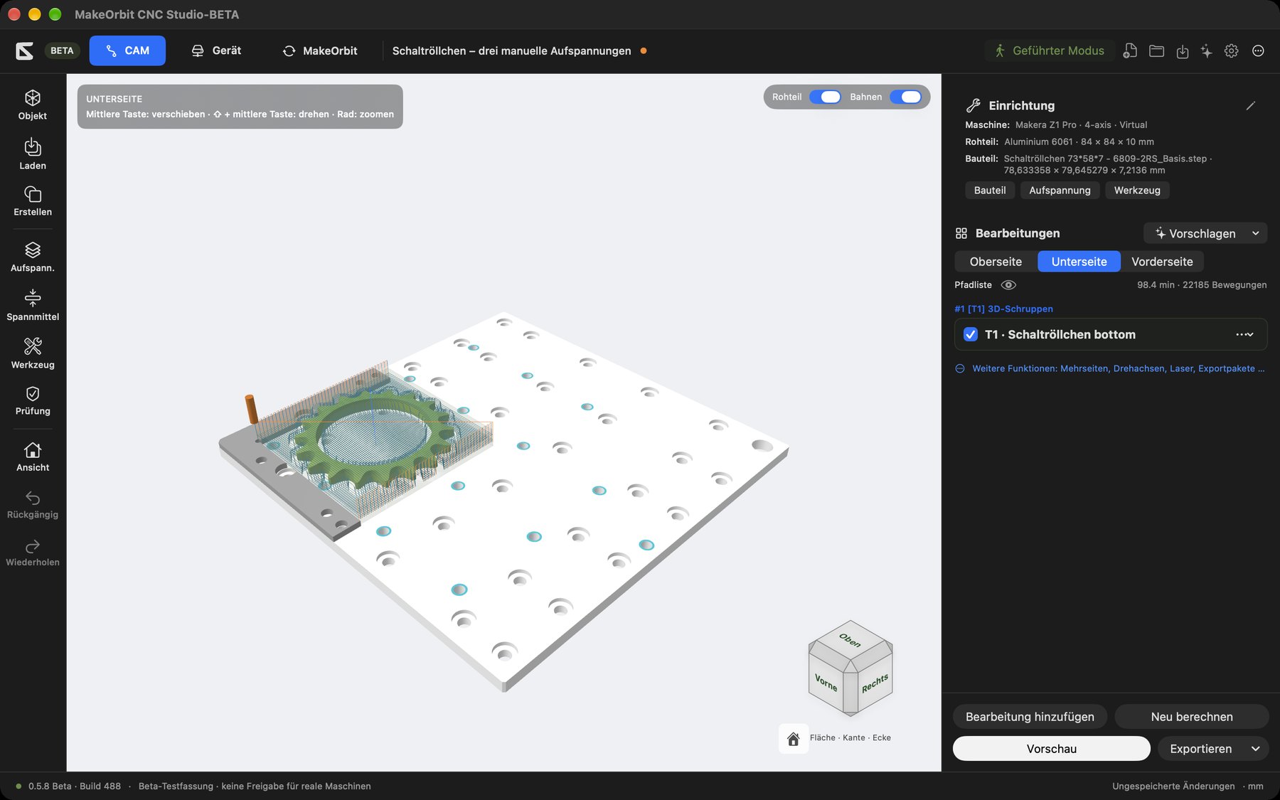
The main window consists of five areas:
| No. | Area | Purpose |
|---|---|---|
| 1 | Top bar | Switch between CAM, Device and MakeOrbit, project name, Guided Mode and icons for New, Open, Save, AI Assistant, Settings and “More Areas” |
| 2 | Left toolbar | Object, Load, Create, Setup, Fixtures, Tool, Check, View, Undo, Redo |
| 3 | 3D workspace | Shows machine table, stock, part, fixtures and milling paths |
| 4 | Right CAM panel | Setup (machine, stock, part) and list of operations |
| 5 | Footer | Version, save status and unit of measurement |
Top bar
- CAM — planning: this is where you spend most of your time.
- Device — machines, connections and monitoring (see Device).
- MakeOrbit — connection to the 645DF MakeOrbit app (see MakeOrbit).
- Project name — an orange dot means unsaved changes.
- Guided Mode — step-by-step help for beginners.
- Icons on the right: New Project, Open, Save, AI Assistant (sparkles icon), Settings (gear) and More (circle with three dots).
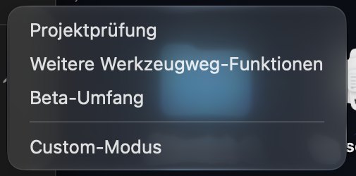
The More menu contains:
- Project Check — all project notices and warnings.
- More Toolpath Functions — special functions such as multi-sided export, rotary axes, laser, export packages and tool-change planning.
- Beta Scope — overview of what this test version can and cannot do.
- Custom Mode — expert view with all settings.
Left toolbar
| Icon | Function |
|---|---|
| Object | Select, place, rotate, copy and arrange a part |
| Load | Import models or drawings: STEP, STL, 3MF, SVG/DXF, image |
| Create | Create simple solids and drawings: block, cylinder, truncated cone, 2D drawing |
| Setup | Define sides, zero points and stock position |
| Fixtures | Add a clamp (automatically on the next free hole for the Makera Z1) |
| Tool | Tool library, available cutters and tool holding |
| Check | Project check with notices and warnings |
| View | Reset view (Home) |
| Undo / Redo | Undo or redo recent changes (up to 20 steps) |
Navigating the 3D workspace
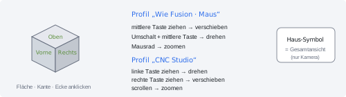
Navigation depends on the selected navigation profile in Settings. A short reminder of the current mouse controls is always shown at the top left of the workspace.
“Like Fusion · Mouse” profile (as in Autodesk Fusion 360):
- Drag with the middle mouse button: pan the view.
- ⇧ + drag with the middle mouse button: orbit the view.
- Ctrl + ⇧ + drag with the middle mouse button or mouse wheel: zoom.
“CNC Studio” profile:
- Drag with the left button: orbit the view.
- Drag with the right button: pan the view.
- Scroll: zoom.
Trackpad: Scroll or pinch to zoom. Scrolling direction automatically follows your macOS setting.
- View cube (bottom right): clicking a face, edge or corner turns the view in that direction (26 directions). Zoom is preserved.
- House icon next to the cube (or View on the left): overall view. This is only a camera movement — it does not home the machine.
- Switches at the top right: show or hide Stock and Paths.
- Information box at the top left: shows the current side (e.g. “TOP SIDE”) and the mouse controls.
The CAM panel
Setup shows the machine, stock and part. The Part, Setup and Tool buttons open the respective pages; the pencil opens the setup assistant.
Operations shows all planned machining steps. Each operation appears as a card “#1 [T1] Strategy” — the sequence number, tool number and type of operation. Above it:
- Side tabs (e.g. “Top”, “Bottom”, “Front”) for multiple setups.
- Suggest — automatic suggestions requiring confirmation (see Automatic suggestions).
- Path list with an eye icon (show/hide paths) and a total, e.g. “98.4 min · 22185 moves”.
- The More functions: multiple sides, rotary axes, laser, export packages … link opens the special functions.
Four fixed buttons are always at the bottom: Add Operation · Recalculate · Preview · Export.
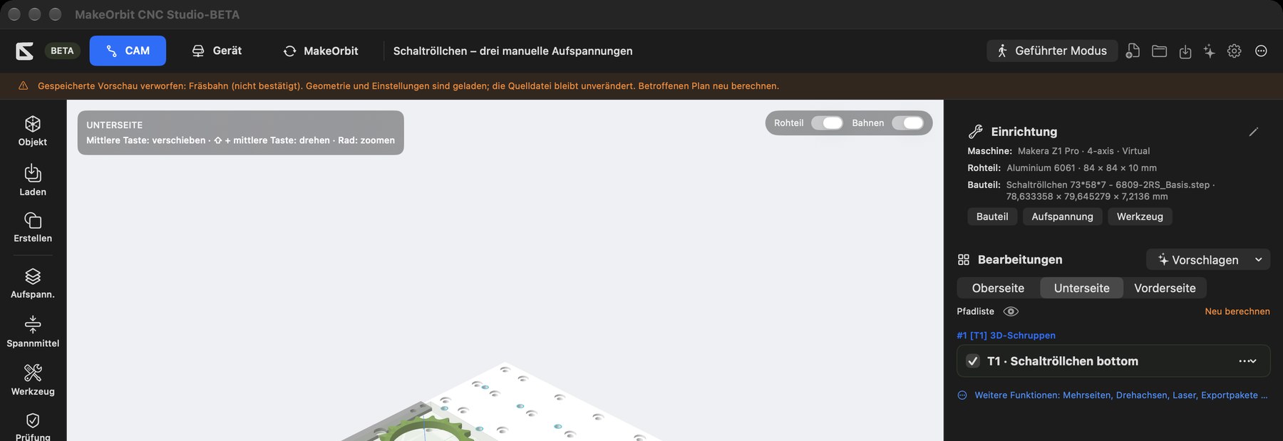
If a saved path is found to be no longer valid when a project opens, an orange notice bar appears at the top (e.g. “Saved preview discarded … Recalculate the affected plan”). Your geometry and settings are preserved in full — simply click Recalculate.
Footer
On the left are the version and the notice “Beta test version · not approved for real machines”; on the right are the save status (“Saved state”, “Unsaved changes”, “New project”) and the unit of measurement (mm or inches).