Documentation · 4 November 2026 · 0.5.8 / Build 488
Complete English guide. Screenshots show the German interface; their captions are translated.
Welcome
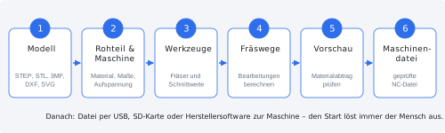
MakeOrbit CNC Studio is an application in which you use your computer to define how a CNC mill (or a laser module) should machine a workpiece. You load a 3D model or a drawing, choose the material and tool, and the application calculates the milling paths from these inputs. The result is a machine file (“NC file” or “G-code”) for your machine to execute.
This guide is written for people who have never worked with CNC before. Technical terms are explained when they first appear; there is also a glossary at the end. Experienced users can go straight to the chapters that interest them — every chapter is accessible from the chapter overview.
How to read this guide
Every function has a status label:
Status: AVAILABLE — The function is usable and tested in the beta.
Status: EXPERIMENTAL — The function is usable, but so far has only been checked computationally or on virtual (simulated) machines. Check the results yourself before using them on real equipment.
Status: IN DEVELOPMENT — The function is planned or partially prepared, but is not yet ready for you to use. It is mentioned here so you know what is coming.
Keyboard shortcuts use Mac notation: ⌘ = Command (cmd), ⇧ = Shift, ⌥ = Option (alt/option).
Why MakeOrbit CNC Studio?
MakeOrbit CNC Studio brings planning for different machines together in one interface. You can load models, define stock and tools, plan operations and generate suitable NC files.
Benefits in everyday work
A continuous workflow: from the model through operations and preview to file export.
Portable project: The .mocnc format contains geometry, stock, setups and results.
Beginners and experienced users: Guided Mode with eight steps, or direct access to machining parameters.
Verifiable output: Export control reads the NC file back in and compares it with the calculated path. This is not approval for running a machine.
Shared master data: With MakeOrbit installed and licensed on your Mac, tools, materials and project archives can be connected.
Optional AI: Suggestions are possible, but manual work does not require an AI account.
German and English: Both languages are provided for in the app; the documented version runs on macOS 15 or later. Windows is in preparation.
Machine profiles and limitations
Own planning profiles for Makera, STEPCRAFT, TwoTrees and user-defined machines support preparation. They are not manufacturer approvals. Manufacturer-specific exports and rotary-axis functions are experimental; direct control of real machines and comprehensive machine collision checking are still in development.
CNC basics in five minutes
Before you start, here are a few terms you will encounter repeatedly in this guide.
What does a CNC mill do?
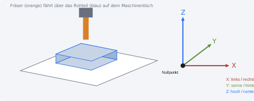
A CNC mill uses computer control to move a rapidly rotating tool — the milling cutter — through a piece of material called the stock. Material is removed layer by layer until the intended part remains. “CNC” stands for Computerized Numerical Control.
The X, Y and Z axes
X — left/right
Y — front/back
Z — up/down
A — rotary axis around X (only machines with a 4th axis, e.g. Makera Z1 Pro with rotary module)
The zero point (also “workpiece zero”) is the point from which all movements are measured. It is usually a corner or the centre of the stock’s top face.
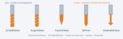
Tools
Flat end mill: The all-rounder for pockets, contours and flat faces.
Ball-nose cutter: Rounded at the tip, for smooth 3D surfaces.
Chamfer and engraving cutters: Tapered to a point, for bevelled edges and engravings.
Drill: For round holes.
Thread mill: For internal and external threads.
Corn-cob cutter: Coarse serrations for rapid material removal (a subgroup of end mills).
Every cutter has a shank (the part held in the holder) and a cutting edge (the part that cuts). The shank is clamped in a collet, whose diameter must match the shank (e.g. 3.175 mm, 4 mm or 6 mm).
Cutting parameters
Spindle speed (rpm): how quickly the cutter rotates.
Feed (mm/min): how quickly the cutter moves through the material.
Stepdown (mm): how deeply the cutter enters the material per pass.
Stepover (mm or %): the distance between two neighbouring milling paths.
MakeOrbit CNC Studio takes these values from a checked tool catalog. You do not need to know them in Guided Mode.
Roughing and finishing
Roughing: Removing a large amount of material quickly. The surface stays rough and a small allowance (remaining material, e.g. 0.2 mm) is left.
Finishing: Producing the final surface slowly and precisely.
Fixtures and setups
The stock must be held firmly on the machine. Fixtures (clamps, jaws, a vise) are used for this. The way the stock is positioned and secured on the machine is called a setup. If a part is machined from several sides, each side needs its own setup.
Tabs and spoilboard
If a part is cut completely out of a sheet, it would come loose at the end and could be thrown around. Small tabs are therefore left in place; you subsequently separate them with a saw or file. A spoilboard underneath the stock protects the machine table during through-cutting.
NC file and postprocessor
The NC file (also G-code) is the list of commands the machine executes. Each machine controller understands a slightly different dialect. The postprocessor (“post”) translates the calculated milling paths into the exact dialect of your machine.
Installation and first launch
Status: AVAILABLE
Requirements
Mac with macOS 15 or later (Apple Silicon or Intel). The application is a universal app.
Recommended: mouse with a middle button or a trackpad.
Optional: the 645DFMakeOrbit app for tool, material and archive management.
Windows: IN DEVELOPMENT — a Windows version will follow later.
Installation
The public beta test has not started yet. There is currently no app download or registration here. The following steps describe installation after a future release has been authorized.
Use only an app file released by 645DF.
Drag MakeOrbit CNC Studio-BETA into the Applications folder.
Follow the installation instructions supplied with the released version. Do not bypass security warnings; ask 645DF about unclear messages.
The version appears at the bottom left in the footer, e.g. “0.5.8 Beta · Build 488 · Beta test version · not approved for real machines”.
The beta runs separately from older test versions: it has its own data folder and its own settings.
Trial period and license
Status: IN DEVELOPMENT — Purchase and online activation are prepared, but not yet enabled.
Planned licensing model:
14-day free trial — from the first launch, including completely offline, without an account.
€69.00 per year (gross) including two permanently assigned machines.
Each additional machine €10.00 per year. If added during the year, it is charged proportionately in full months until the license expires.
One person, two computers (Mac and/or Windows), including simultaneous use.
One-time online confirmation of the license key; usable offline afterwards until the license expires.
Renewal manually or automatically on request.
Reminders 60, 30, 14, 7 and 1 day before expiry.
All projects are retained after expiry; the application then opens only for license management.
Later: Enterprise packages for 5, 10, 20 and 50 machines.
Purely virtual planning profiles and exporting machine files alone occupy no machine slot. A slot is required only for direct connection to and control of a real machine.
The interface
Status: AVAILABLE
The main window consists of five areas:
No.
Area
Purpose
1
Top bar
Switch between CAM, Device and MakeOrbit, project name, Guided Mode and icons for New, Open, Save, AI Assistant, Settings and “More Areas”
Add a clamp (automatically on the next free hole for the Makera Z1)
Tool
Tool library, available cutters and tool holding
Check
Project check with notices and warnings
View
Reset view (Home)
Undo / Redo
Undo or redo recent changes (up to 20 steps)
Navigating the 3D workspace
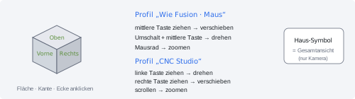
Navigation depends on the selected navigation profile in Settings. A short reminder of the current mouse controls is always shown at the top left of the workspace.
“Like Fusion · Mouse” profile (as in Autodesk Fusion 360):
Drag with the middle mouse button: pan the view.
⇧ + drag with the middle mouse button: orbit the view.
Ctrl + ⇧ + drag with the middle mouse button or mouse wheel: zoom.
“CNC Studio” profile:
Drag with the left button: orbit the view.
Drag with the right button: pan the view.
Scroll: zoom.
Trackpad: Scroll or pinch to zoom. Scrolling direction automatically follows your macOS setting.
View cube (bottom right): clicking a face, edge or corner turns the view in that direction (26 directions). Zoom is preserved.
House icon next to the cube (or View on the left): overall view. This is only a camera movement — it does not home the machine.
Switches at the top right: show or hide Stock and Paths.
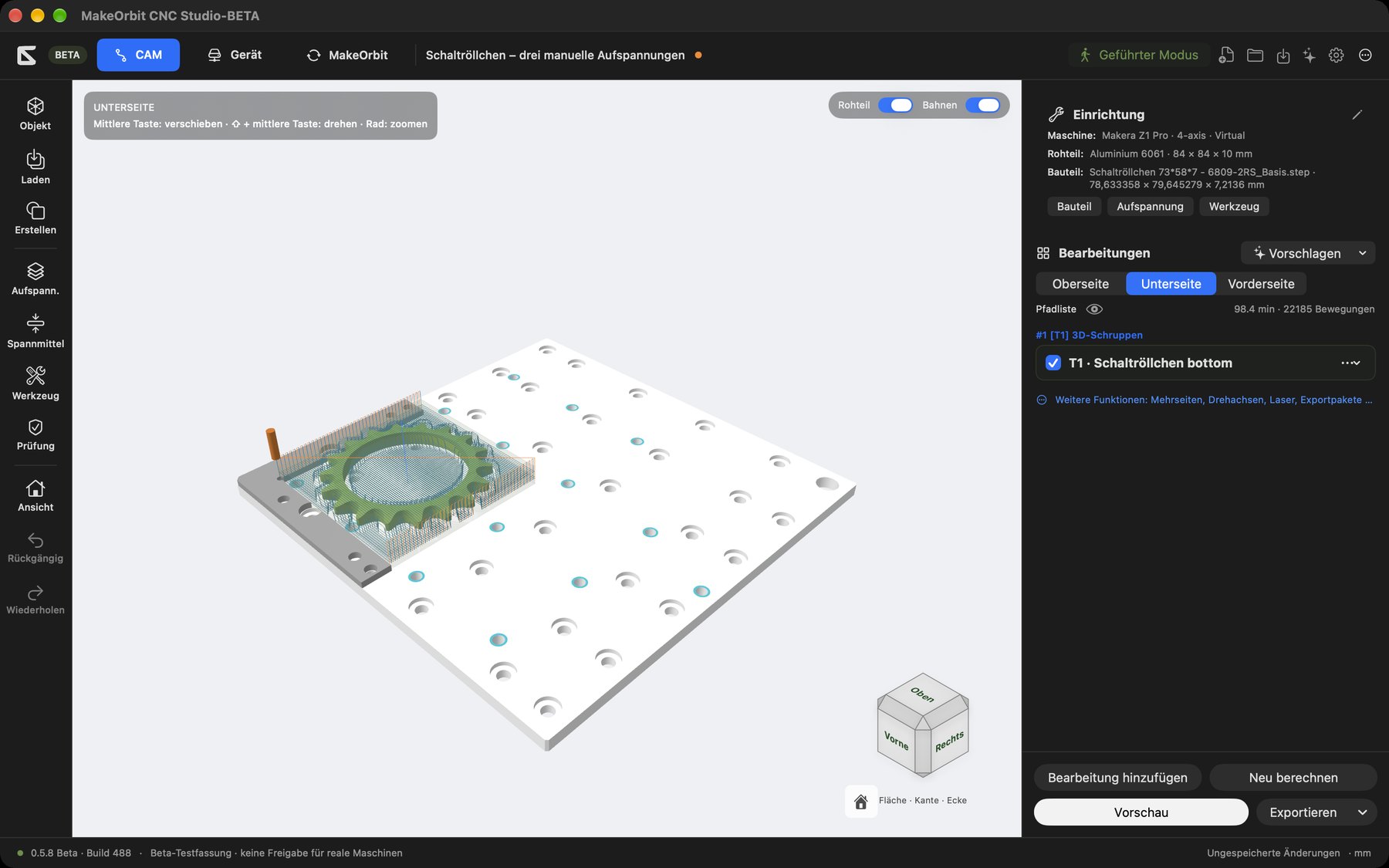
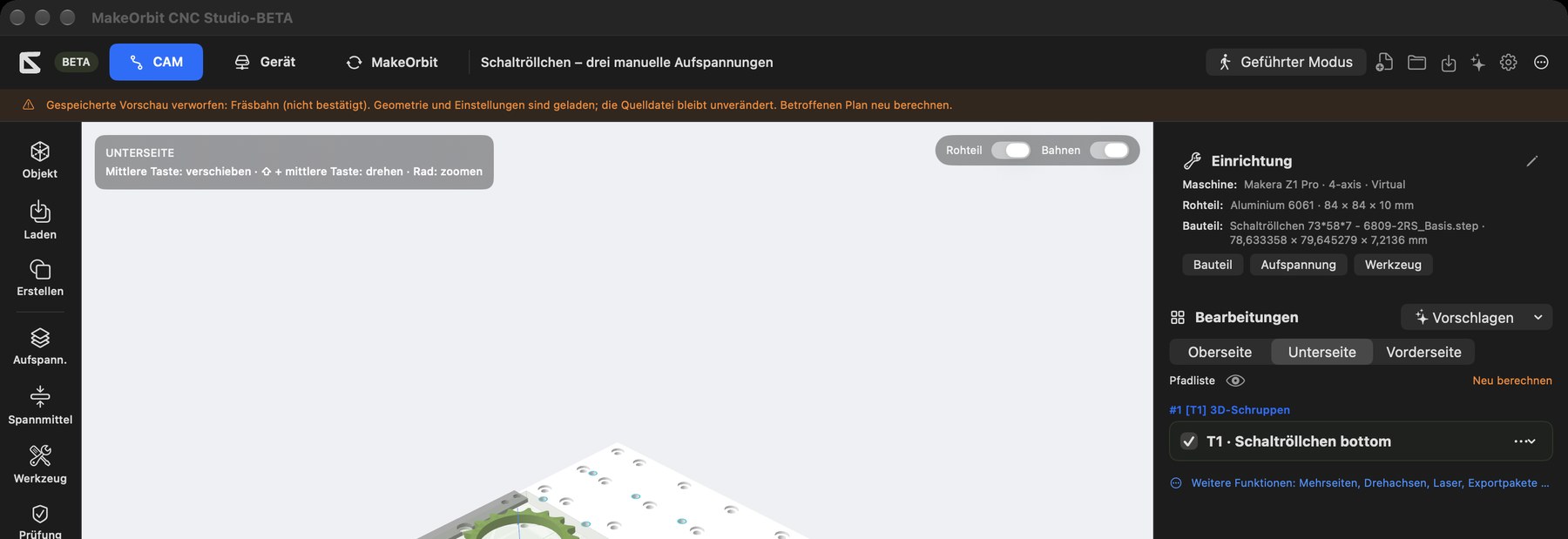
Information box at the top left: shows the current side (e.g. “TOP SIDE”) and the mouse controls.
The CAM panel
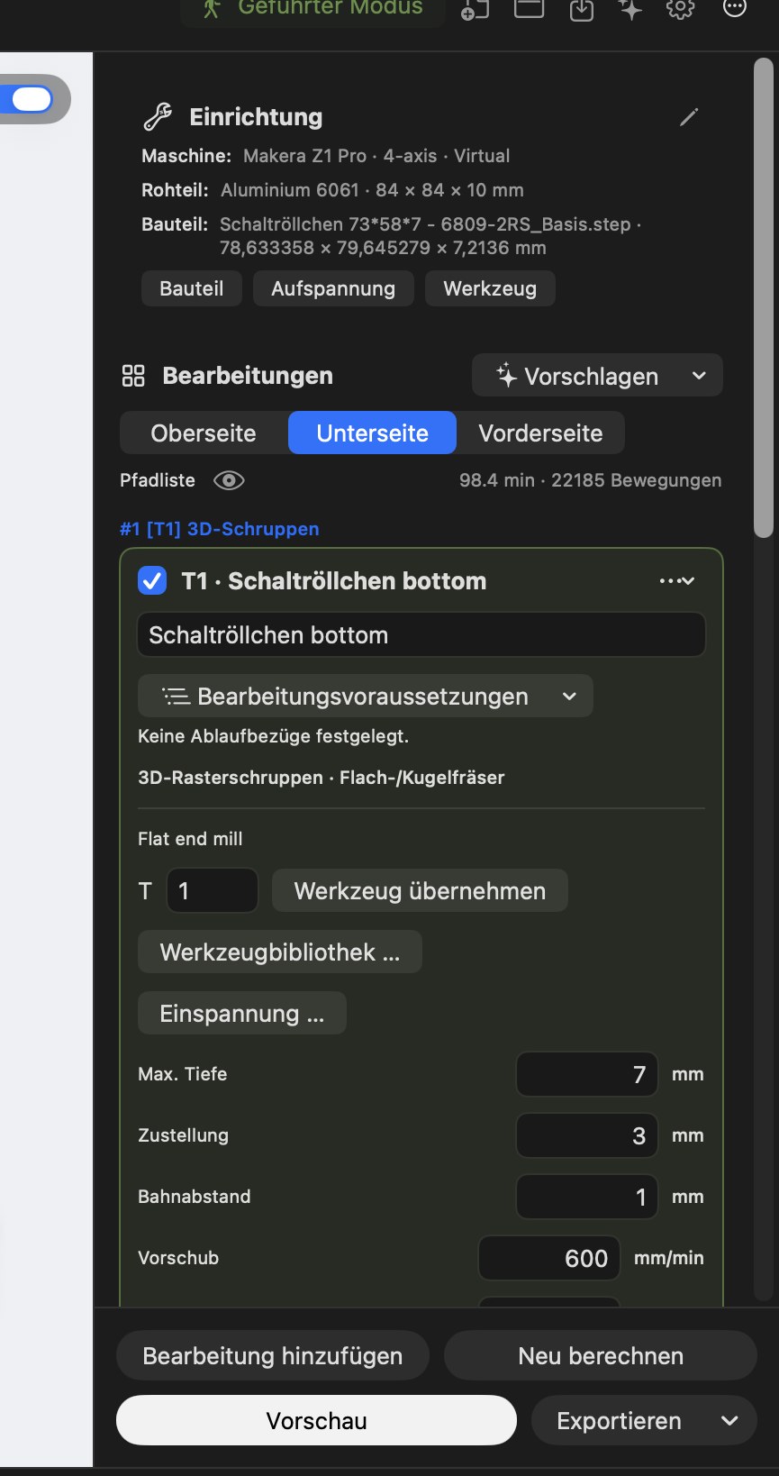
Setup shows the machine, stock and part. The Part, Setup and Tool buttons open the respective pages; the pencil opens the setup assistant.
Operations shows all planned machining steps. Each operation appears as a card “#1 [T1] Strategy” — the sequence number, tool number and type of operation. Above it:
Side tabs (e.g. “Top”, “Bottom”, “Front”) for multiple setups.
Path list with an eye icon (show/hide paths) and a total, e.g. “98.4 min · 22185 moves”.
The More functions: multiple sides, rotary axes, laser, export packages … link opens the special functions.
Four fixed buttons are always at the bottom: Add Operation · Recalculate · Preview · Export.
If a saved path is found to be no longer valid when a project opens, an orange notice bar appears at the top (e.g. “Saved preview discarded … Recalculate the affected plan”). Your geometry and settings are preserved in full — simply click Recalculate.
Footer
On the left are the version and the notice “Beta test version · not approved for real machines”; on the right are the save status (“Saved state”, “Unsaved changes”, “New project”) and the unit of measurement (mm or inches).
Create a new project
Status: AVAILABLE
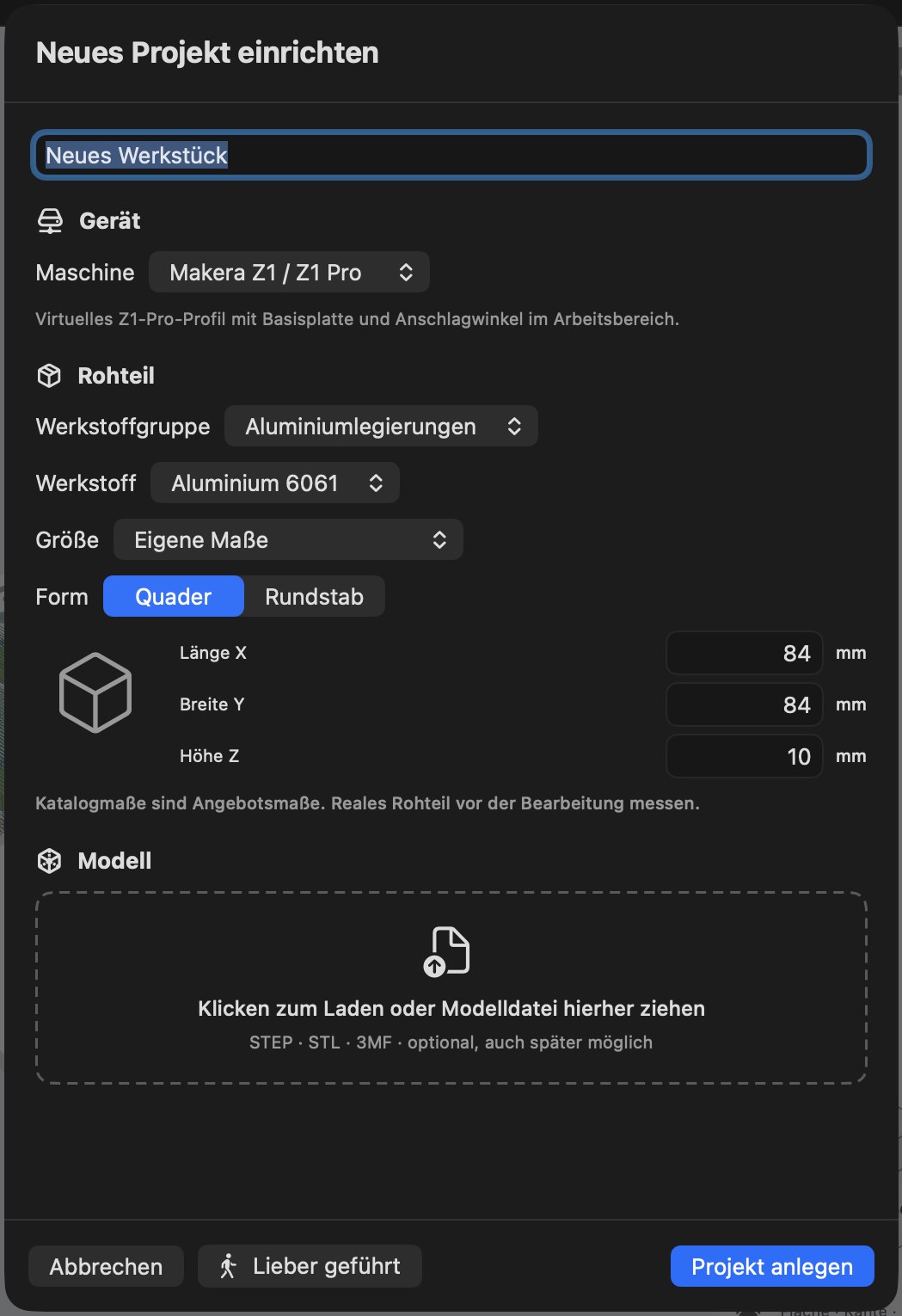
Start a new project with ⌘N, through File › New Project … or using the icon in the top bar. The setup assistant opens.
Enter a project name at the top (default: “New workpiece”).
Step 1: Choose a device
Under Machine, choose your mill: Makera Z1 / Z1 Pro, Makera Carvera, Makera Carvera Air or a custom machine from your library. The profile defines the working envelope and spindle-speed and feed limits. For the Makera Z1, the base plate with its corner stop and holes appears in the workspace.
Step 2: Define the stock
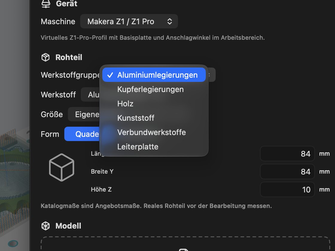
Choose the material group: aluminium, copper alloys, wood, plastic, composites or circuit board.
Choose the material, e.g. aluminium 6061, aluminium 7075, brass, copper, POM (Delrin), acrylic (PMMA), carbon fibre (CFRP).
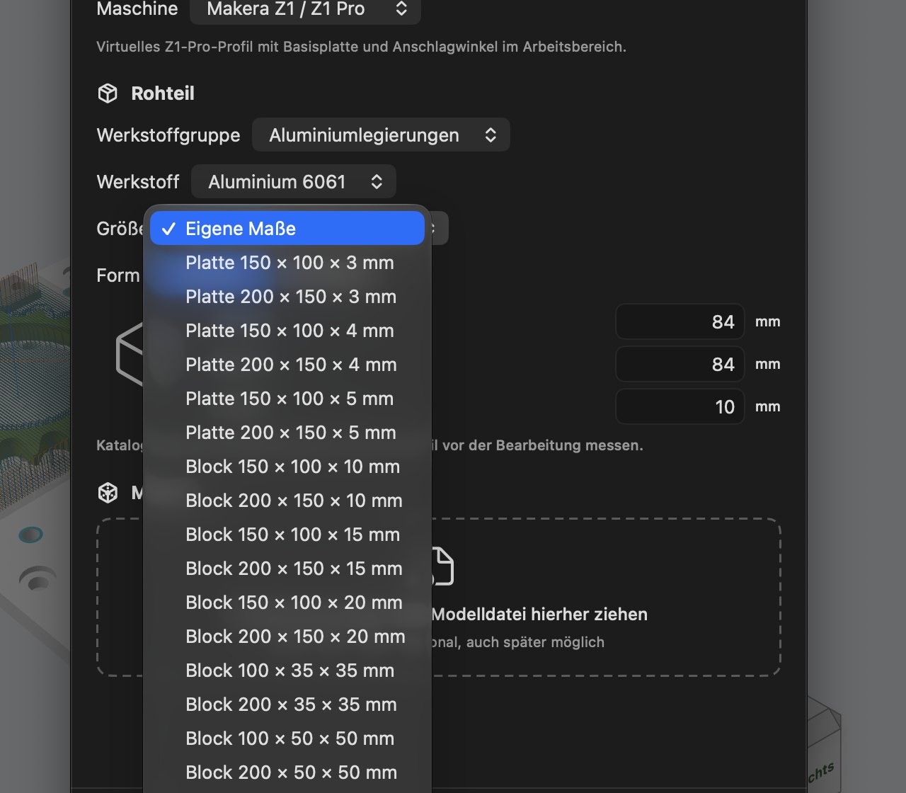
Choose a size from the catalog (189 templates for sheets, blocks and round bars, e.g. “Sheet 200 × 150 × 5 mm” or “Block 100 × 50 × 50 mm”) or Custom dimensions with length X, width Y and height Z.
Shape: block or round bar.
Tip: Always measure your stock with calipers. The app points out: “Catalog dimensions are nominal supplier dimensions. Measure the real stock before machining.” The catalog contains no size templates for wood — enter your own dimensions for it.
Custom materials: You can create your own material names through the material menu. The application recognizes duplicates and typing errors (“Did you mean brass?”). With an active connection, materials can be taken from MakeOrbit. There are no catalog cutting parameters for custom materials.
Step 3: Load a model
Click the field or drag a STEP, STL or 3MF file into it. This is optional; you can also load the model later.
Prefer guided? This button starts Guided Mode instead of a normal project.
Create Project opens the project directly in CAM view. You can return to the assistant at any time using the pencil in the setup card.
Guided Mode — step by step to your first part
Status: AVAILABLE
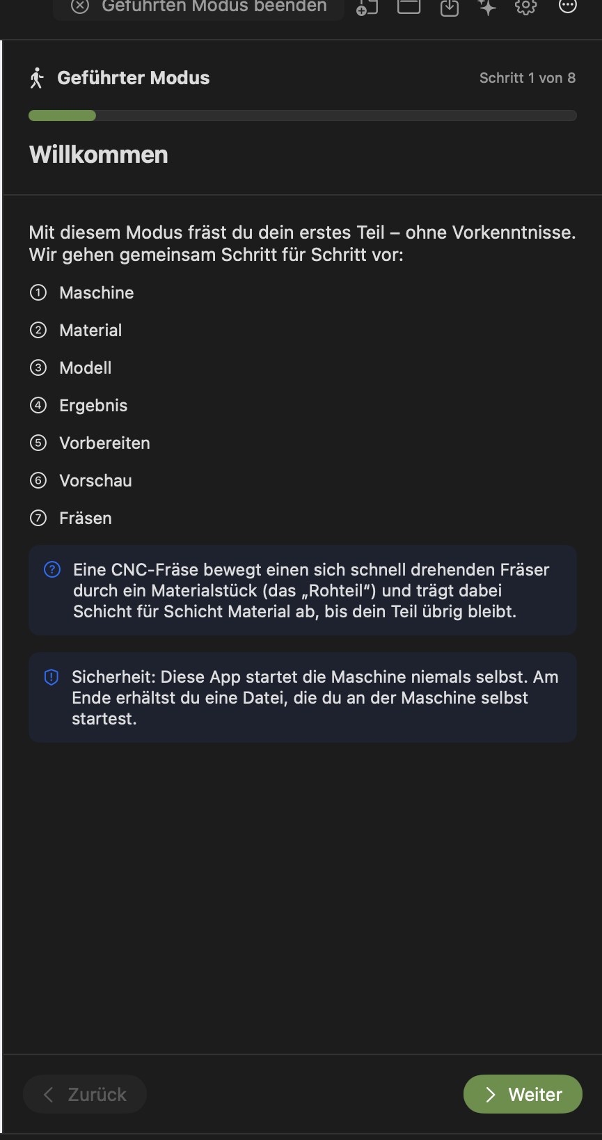
Guided Mode is intended for anyone who has never milled before. The application asks simple questions and handles the technical decisions. Start it with the Guided Mode button at the top, ⇧⌘G, or Prefer guided in the setup assistant.
On the right you see “Step n of 8”, a progress bar, and Back and Next. The 3D workspace remains visible.
Step 1: Welcome
A short explanation of what a CNC mill does, how the workflow works, and that the application never starts the machine itself.
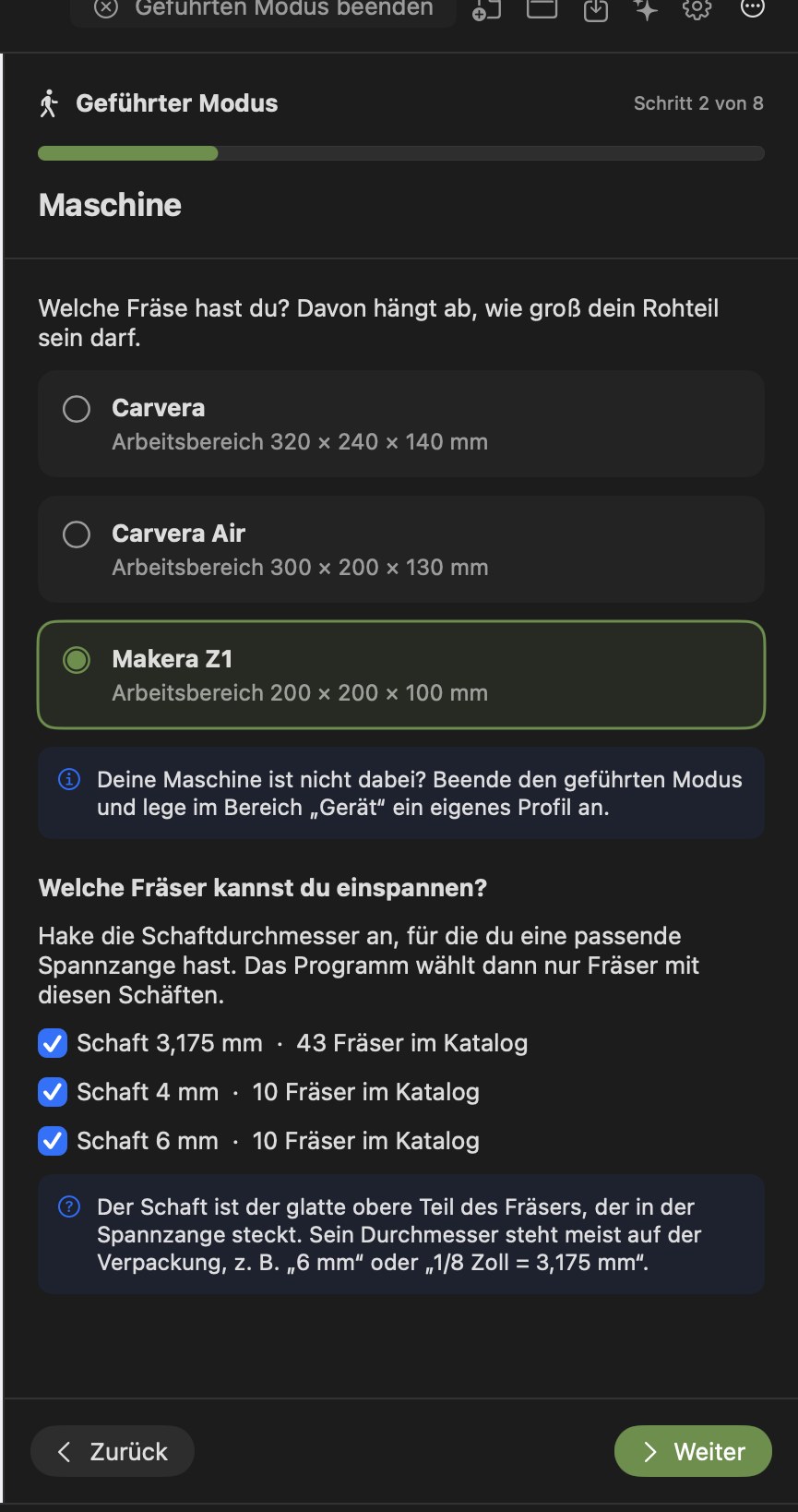
Step 2: Machine
“Which mill do you have?” — the choices are:
Machine
Working envelope
Carvera
320 × 240 × 140 mm
Carvera Air
300 × 200 × 130 mm
Makera Z1
200 × 200 × 100 mm
If your machine is not listed, exit Guided Mode and create a custom profile in Device.
Below, answer “Which cutters can you clamp?”: tick the shank diameters for which you have a matching collet — e.g. 3.175 mm shank (43 cutters in the catalog), 4 mm shank (10 cutters) and 6 mm shank (10 cutters). The application then plans only with cutters you can actually clamp. A tip from the app: the shank diameter is usually printed on the packaging, e.g. “6 mm” or “1/8 inch = 3.175 mm”.
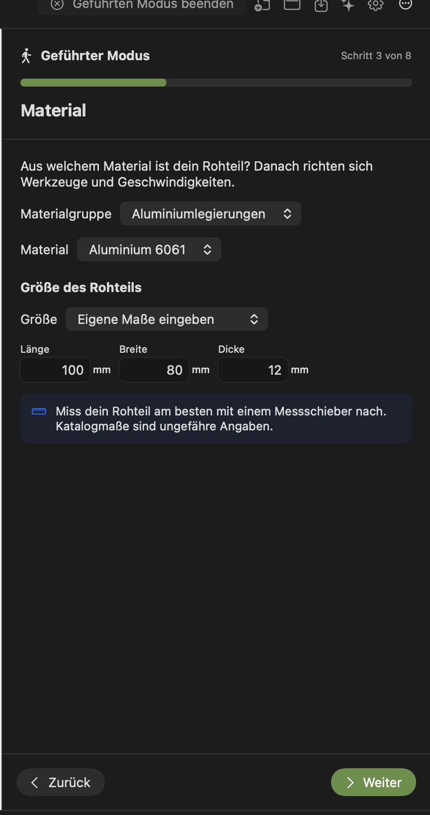
Step 3: Material
“What material is your stock made of?” — material group, material and stock size (length, width, thickness), as in the setup assistant. The notice reminds you: “It is best to measure your stock with calipers.”
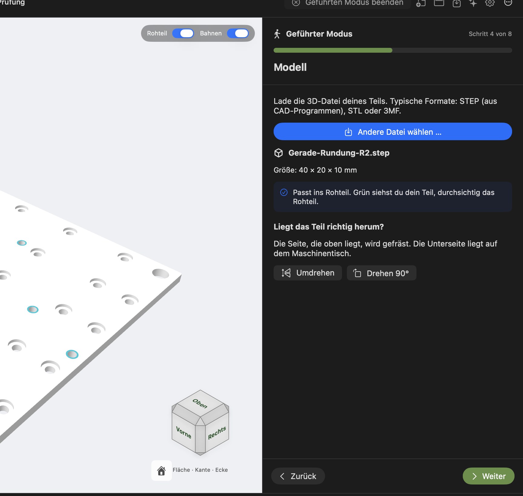
Step 4: Model
Use Select File … to load a 3D model (STEP from CAD applications, STL or 3MF) or a 2D drawing (DXF or SVG). For a model, the application shows the file name, the size, and whether the part fits in the stock (“Your part is shown in green; the stock is transparent”).
2D drawing (DXF/SVG): The drawing is centred on the top face of the stock and shown in blue. The app shows its size and the number of closed shapes and open lines, and warns if the drawing is larger than the stock. Status: EXPERIMENTAL — checked computationally and virtually.
For a 3D model, under “Is the part the right way up?”, remember: the top side will be milled; the underside rests on the machine table. Use Flip and Rotate 90° to orient the part correctly.
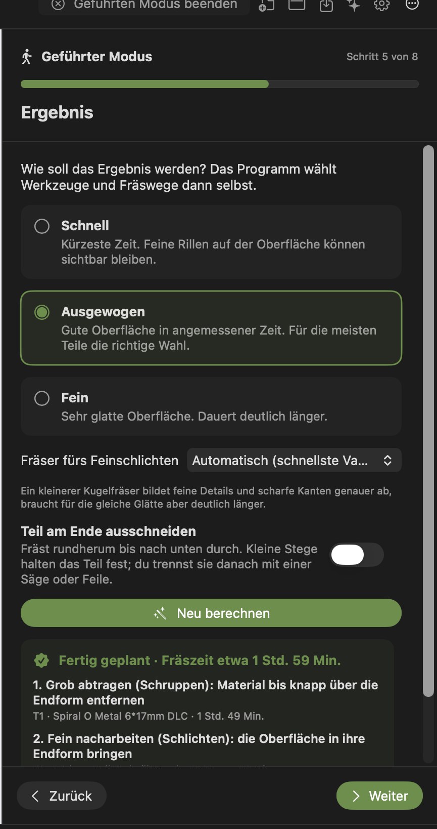
Step 5: Result
For a 3D model, choose the desired quality:
Fast — shortest time; fine grooves may remain visible.
Balanced — a good surface in a reasonable time (right for most parts).
Fine — a very smooth surface; takes considerably longer.
Optional:
Cut out the part at the end — mills all the way around and through to the bottom; four small tabs hold the part in place.
Fine-finishing cutter — “Automatic” (fastest variant) or a specific ball size.
For a 2D drawing, choose what to do:
Cut out — mills closed shapes through the stock, starting with inner holes and then the outer profile with four small holding tabs. Put a spoilboard underneath.
Recess (pockets) — clears the area inside closed shapes to the selected depth and leaves inner shapes as islands. Internal corners retain the cutter radius.
Engrave lines — follows the centre of all lines, including open ones such as lettering. A depth of 0.3 to 1 mm is often sufficient. The cutter diameter determines the line width.
The app compares up to three cutter sizes from the catalog and selects the fastest fully calculated option. For engraving it uses the finest cutter. Cut-out and recess ignore open lines and report this in the result.
Work zero at the machine — before calculating, choose where to set X, Y and Z on the machine: Bottom · Centre, Top · Centre, or Top · Front-left corner. A plain-language description appears below the choice. “Top” sets Z at the stock surface, while “Bottom” sets Z at the supporting face, which can suit cut-out jobs. Changing the zero requires recalculation.
With Calculate Plan, the application creates the complete plan: roughing with the largest suitable flat end mill, finishing with a ball-nose cutter, and optionally cutting out with a ramp and tabs. If the project already has operations, they are replaced (Undo remains available). Calculation runs in the background and can be cancelled.
Afterwards, for example, “Planning complete · Milling time approximately 1 hr 59 min” appears with the individual steps in plain language:
Remove bulk material (roughing): remove material to just above the final shape — e.g. T1 · 6 mm flat end mill.
If needed: Remove remaining material (rest roughing) with a smaller cutter where the larger one could not reach — e.g. T3 · 4 mm flat end mill.
Refine the surface (finishing): bring the surface to its final shape — e.g. T2 · 4 mm ball-nose cutter.
Optional: Cut out with tabs.
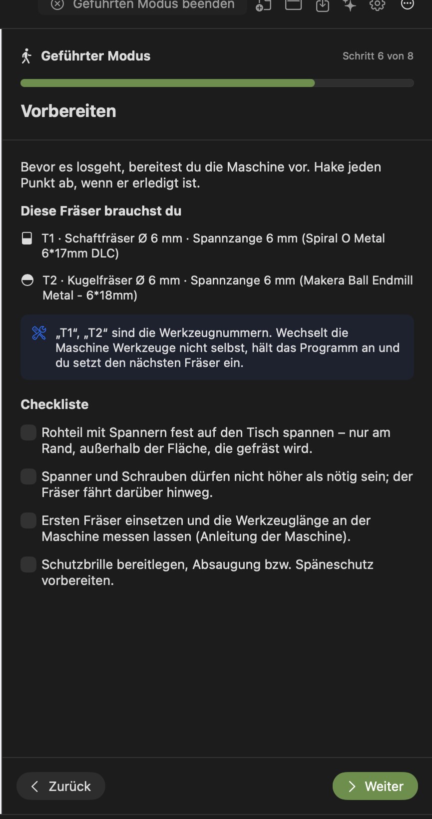
Step 6: Prepare
“These are the cutters you need”: a list with tool number (T1, T2 …), type, diameter, matching collet and catalog name. The app explains: “T1” and “T2” are tool numbers — if the machine does not change tools automatically, the program stops and you insert the next cutter.
There is also a checklist to tick off:
Clamp the stock firmly to the table — only at the edges, outside the area to be milled.
Clamps and screws should be no higher than necessary; the cutter travels over them.
Insert the first cutter and have its tool length measured at the machine.
Have safety glasses ready and prepare extraction or chip protection.
When cutting out: place a spoilboard underneath.
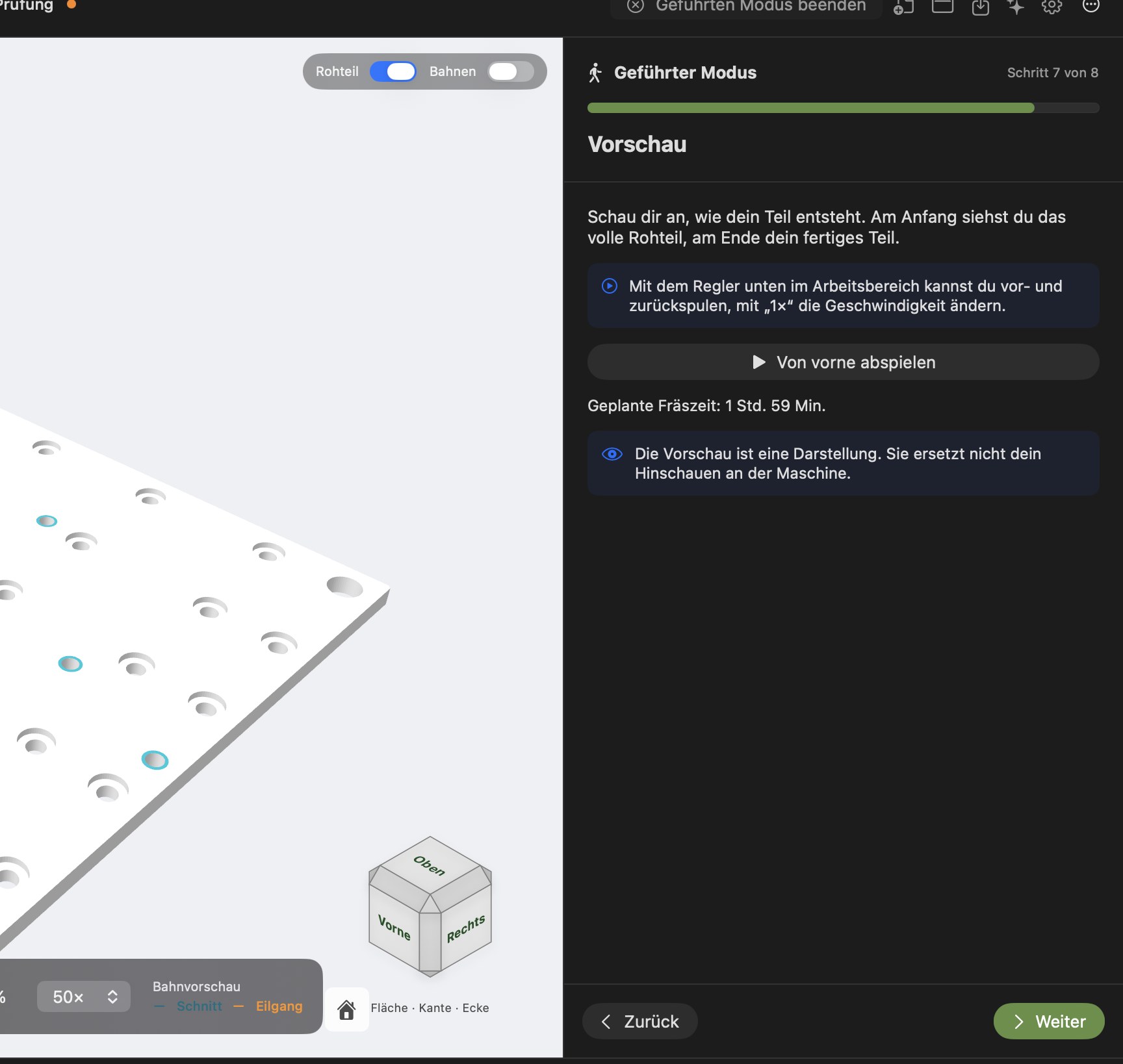
Step 7: Preview
The live preview starts automatically: at the beginning you see the full stock; at the end, your finished part. Use the slider at the bottom to move backwards and forwards, and “1×” through “50×” to change playback speed. Play from the beginning restarts it. The planned milling time is shown. A notice in the app says: “The preview is a visualization. It does not replace watching what happens at the machine.”
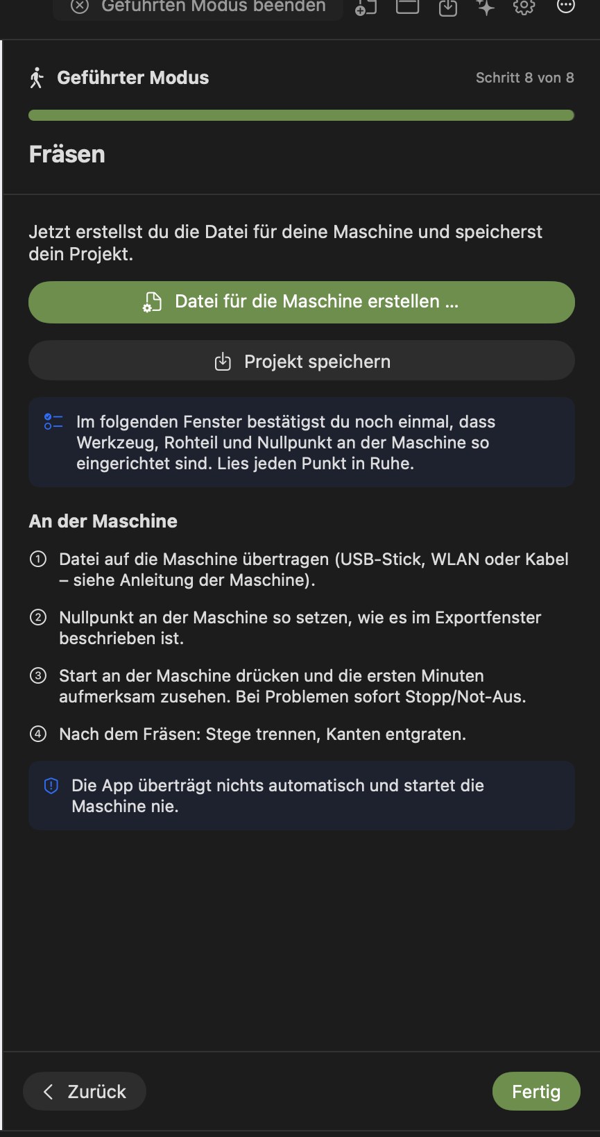
Step 8: Mill
Create File for the Machine … — opens export control and generates the machine file. For Makera Z1, Guided Mode uses the “Makera Z1 Pro · XYZ” planning profile, which is maintained by 645DF and has no manufacturer approval, and generates Z1 files, one per machining step. These files contain no automatic tool change or homing cycle. Other machines without a dedicated format receive a checked NC draft. Confirm all four setup conditions again for the Z1 export. Check the tool, stock, workholding and work zero. The window describes the work zero in plain language.
Save Project.
At the machine: transfer the file (USB stick, Wi-Fi or cable — see your machine’s instructions), set the zero point as described in the export window, press Start at the machine and watch attentively for the first few minutes (use Stop/Emergency Stop immediately if a problem occurs), then separate the tabs and deburr the edges.
“The app does not transfer anything automatically and never starts the machine.”
Use Done or Exit Guided Mode to return to the normal view. Everything Guided Mode planned can be adjusted further there.
Limits of Guided Mode: rectangular stock, machining from above, one part or one drawing. The app can use catalog values for materials such as ABS, acrylic (PMMA), POM, polycarbonate, printed circuit board material (FR4), MDF and CFRP. Catalog values are unavailable for Bakelite, epoxy and engineered stone. Cutting parameters are taken unchanged from the catalog and are deliberately conservative — milling times can therefore be long. Custom cutting parameters are available in expert mode.
The expert-mode workflow
Status: AVAILABLE
Without Guided Mode, work through the following sequence — each step links to the relevant chapter:
exact CAD geometry with faces and edges — recommended
AVAILABLE
STL
triangle mesh (contains no unit — choose source units in mm or inches)
AVAILABLE
3MF
triangle mesh with units, also multiple bodies
AVAILABLE
DXF
2D drawing, including blocks, splines and block arrays
AVAILABLE
SVG
2D drawing (convert text to paths first)
AVAILABLE
Image (PNG/JPG)
for laser engraving and image-to-path
AVAILABLE
.mocad
transfer from Fusion 360 or SolidCraft
AVAILABLE
STEP — the best choice
Status: AVAILABLE
STEP files contain exact geometry. The application recognizes holes, pockets, chamfers and fillets from it and can suggest suitable operations. Units are automatically converted to millimetres. The original is fully embedded in the project file. If an import is cancelled or fails, your existing project remains unchanged.
STL and 3MF — meshes
Status: AVAILABLE
Meshes consist of many small triangles. The application checks them for open edges, duplicate or degenerate triangles and intersecting surfaces, and shows the results as mesh diagnostics. Suspicious triangle pairs can be displayed in the 3D area. Automatic repair is deliberately not performed.
DXF and SVG — 2D drawings
Status: AVAILABLE
2D drawings are used for contours, pockets, drilling, chamfers and laser paths. Supported elements are lines, arcs, circles, ellipses, polylines, splines, blocks, block arrays and local SVG references. Unsupported content is rejected with an explanation rather than silently changed.
Create simple solids and drawings
Status: AVAILABLE
Under Create: Block, Cylinder, Truncated Cone and 2D Drawing (rectangles, circles, ellipses, polygons, mirroring and rectangular arrays). A full parametric CAD system is not intended — use Fusion 360, SolidCraft or another CAD application for that.
Image tracing and relief
Status: EXPERIMENTAL — Image-to-path is usable; relief from images is in development.
Transfer from Fusion 360 and SolidCraft
Status: AVAILABLE
Fusion 360: Use the MakeOrbit add-in to export the active design directly as a .mocad file; CNC Studio imports it automatically.
SolidCraft: Bodies are transferred as STEP/STL/3MF through the companion integration with MakeOrbit. Direct import into CNC Studio is IN DEVELOPMENT.
Position, copy and arrange parts
Status: AVAILABLE
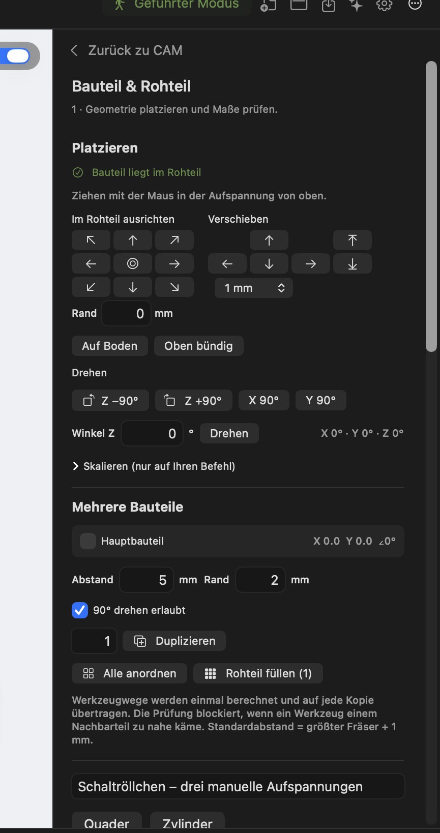
Click Object on the left. The Part & Stock page opens on the right (use Back to CAM to return). At the top, you can see whether the part is inside the stock (e.g. “Part is inside stock”).
Drag with the mouse: move the part in the workspace (snapping to a 0.5 mm grid; hold ⌥ to move freely). ⌘- or ⇧-click selects multiple parts.
Align: 3 × 3 grid (corners, edges, centre) with edge margin; On Bottom and Flush with Top.
Move: arrow controls for X/Y and Z with steps of 0.1 / 1 / 5 / 10 mm.
Rotate: Z ±90°, X 90°, Y 90° and a free angle.
Scale: only on explicit command with confirmation. Warning: STEP and 3MF models are converted to a mesh; CAD-based operations are removed.
Exact X/Y/Z fields for precise values.
Several parts from one piece of stock
Duplicate: adds copies and rearranges them.
Arrange All / Arrange Selection: places parts as compactly as possible in the front-left corner so the remainder of the stock stays contiguous.
Fill Stock (n): shows how many parts fit with the spacing, edge margin and allowed 90° rotation, and creates them (maximum 200).
Spacing between parts (default: largest cutter + 1 mm) and margin to the stock edge (default 2 mm).
Part outline instead of a rectangle: Spacing and overlap checks follow the part outline rather than its bounding rectangle, so round or angled parts can sit closer together. Arrange and Fill Stock also try staggered rows, offsetting every second row by half the pitch. For example, with 4 mm spacing, 28 instead of 24 round parts of 20 mm diameter fit on 112 × 150 mm stock. Inward corners such as those on L-shaped parts are enclosed by an outer outline, so those parts are not nested into one another.
Milling paths are calculated once and transferred to each copy. If the tool comes too close to a neighbouring part, calculation is blocked with a clear message.
Limitation: copies are always repetitions of the same part. Several different parts in one project are IN DEVELOPMENT.
Setups and fixtures
Setups
Status: AVAILABLE
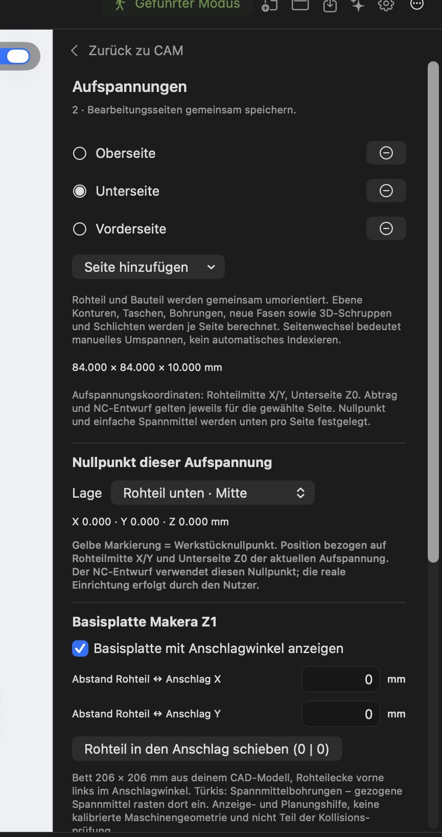
Click Setup on the left. Each setup describes one machining side (top, bottom, front, back, left, right) with its own zero point, fixtures and checks.
On the Setups page:
A list of sides (e.g. top, bottom, front); use Add side to create more.
Zero point of this setup – “Position”, e.g. “Stock bottom · Center”. A yellow marker shows the workpiece zero in the workspace. The machine file uses exactly this zero point; you set it yourself on the machine.
Makera Z1 base plate – displays the base plate with locating angle, the stock ↔ stop distance in X and Y, and the Move stock against the stop button. The turquoise circles are fixture holes where fixtures snap into place.
When a part is machined from several sides, you must reclamp it by hand between sides. The program plans all sides together, keeps the geometry correctly aligned in space and exports a separate machine file for each side.
Fixtures
Status: AVAILABLE
Use Fixtures to add a clamp. On the Makera Z1, it is automatically placed on the next free hole in the base plate. You can move fixtures with the mouse in the 3D area; they snap to the holes (⌥ = free movement). On every calculation, the program checks whether the cutter, neck, shank or holder would touch a registered fixture, and blocks the calculation if so.
Stock and machine workspace
Status: AVAILABLE
The program checks whether the stock and part fit within the working space and whether the tool is long enough. Stock overhang beyond the table is allowed with a warning; axis travel limits are never ignored.
Tools and materials
Status: AVAILABLE
Click Tool on the left. The Tool & Values page shows the default tool for new operations (type, diameter, cutting length, suitability) and the default cutting values (depth from stock top, stepdown, feed, plunge, spindle speed, safety clearance). Open the library with Tool library ….
Tool library
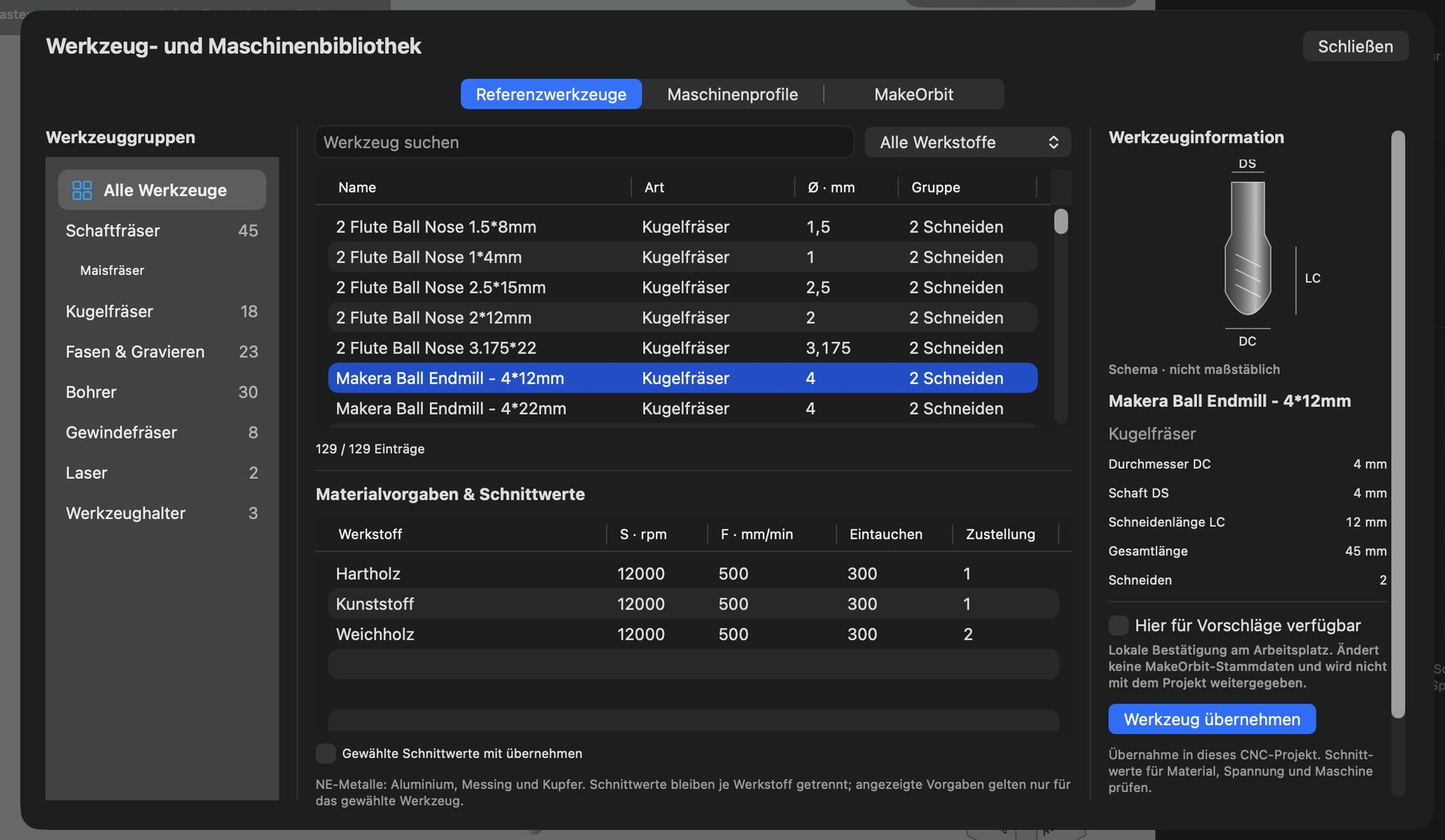
The Tool and machine library has three tabs: Reference tools, Machine profiles and MakeOrbit.
The reference tools area (currently 129 entries) is organized as follows:
Tool groups on the left: end mills (including the corn-cutter subgroup), ball-nose cutters, chamfering & engraving, drills, thread mills, lasers, tool holders.
Tool table in the center, with a search field and material filter (“All materials”).
Below it, Material presets & cutting values: spindle speed (S), feed (F), plunge feed and stepdown for each material.
On the right, Tool information with a schematic drawing (diameter DC, shank DS, cutting length LC, overall length, flute count).
Available here for suggestions – confirms that you own this cutter (see below).
Use tool – inserts the tool into your project; “Also use selected cutting values” includes the values for the selected material.
Each material has its own cutting values. Non-ferrous metals (aluminium, brass, copper) are grouped for searching, but cutting values always apply only to the specific individual material. A cutter approved only for aluminium is never automatically suggested for brass.
Confirm available cutters
Use Available here for suggestions (in the library) or Select available cutters … to tick the cutters you actually own. This confirmation applies only on your computer and is not passed on with the project. Automatic suggestions use only this selection – the full catalog is used only when explicitly requested.
Tool holding and tool numbers
For each cutter, enter its stick-out length (how far it extends from the collet) and the holder height. Each operation has a tool number (T1, T2 …). Conflicts – two different cutters with the same number – are detected and can be resolved, on request, with a suggestion that requires confirmation.
Tool-change planning
Status: EXPERIMENTAL – magazine assignments and virtual automatic changes are planned; the user always confirms real changes.
Warnings
The program warns when a tool and material are unsuitable for one another, when spindle speed or feed falls outside the machine limits, or when no cutting values are available for the selected material. It does not invent values or silently clamp catalog values to limits.
Plan machining operations
An operation is a machining step using one tool, e.g. “Outside contour with a 3-mm end mill”. Click Add operation at the bottom.
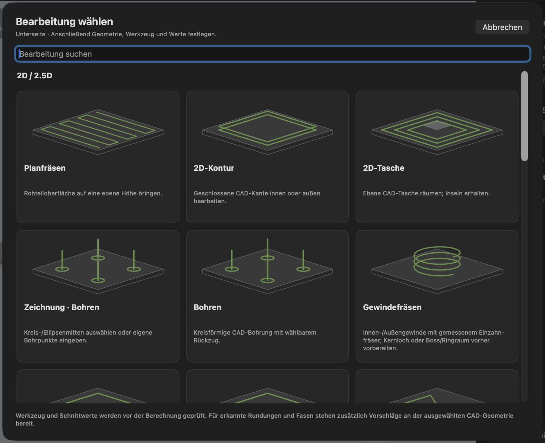
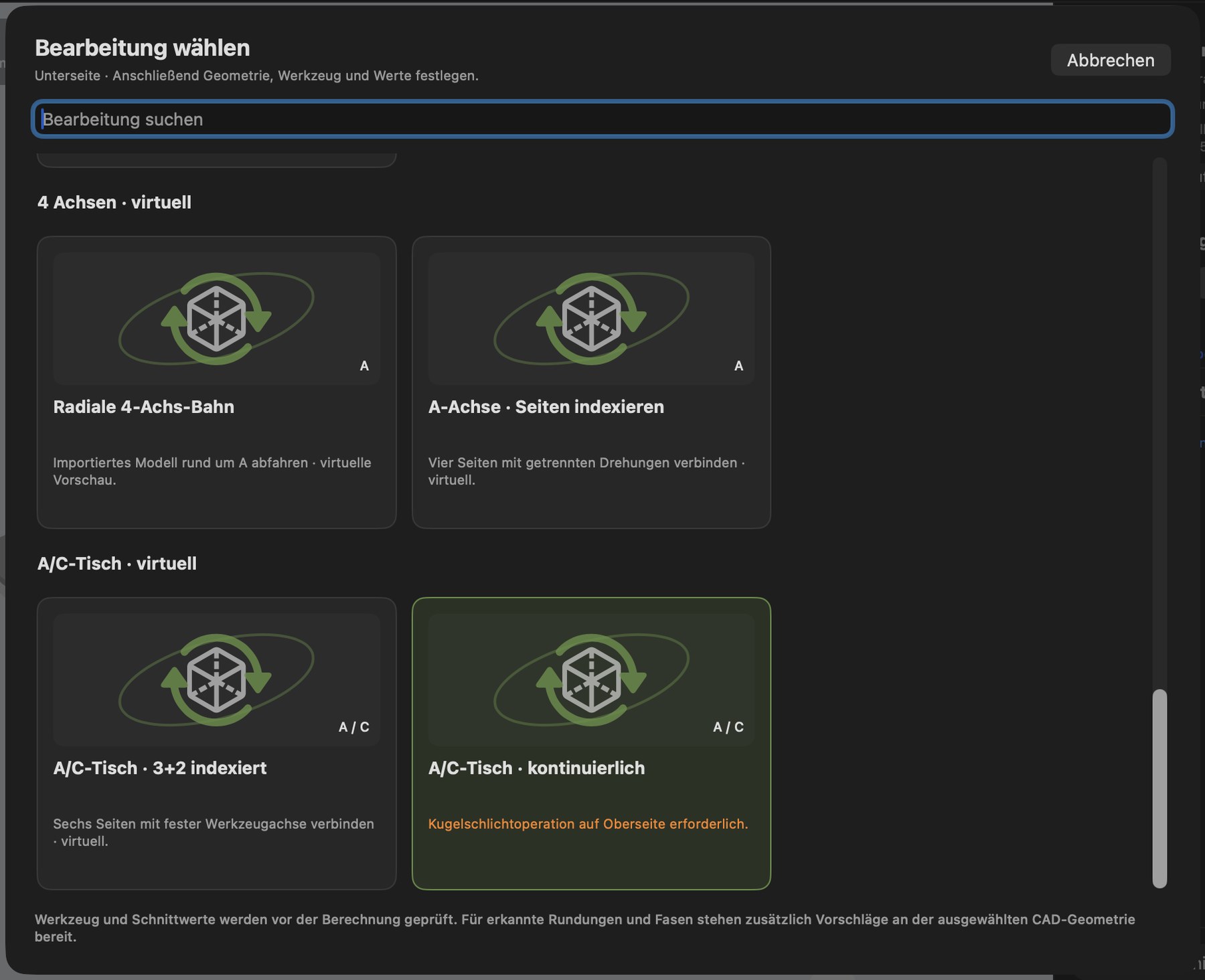
The Choose operation window always applies to the currently selected side. It has a search field and is organized into groups; each card has an image and a short explanation. Strategies whose prerequisites are missing are displayed but disabled, with the reason shown in orange (e.g. “First create a closed drawing in this setup”).
Group
Operation
Short description in the app
2D / 2.5D
Facing
Bring the stock surface to a flat height
2D / 2.5D
2D contour
Machine a closed CAD edge on the inside or outside
2D / 2.5D
2D pocket
Clear a flat CAD pocket; preserve islands
2D / 2.5D
Drawing · Drilling
Select circle/ellipse centers or enter your own drilling points
2D / 2.5D
Drilling
Circular CAD hole with selectable retract
2D / 2.5D
Thread milling
Internal/external threads using a measured single-tooth cutter
2D / 2.5D
Edge chamfer
Machine a planar chain of edges with a chamfer cutter
2D / 2.5D
Drawing · Chamfer
Chamfer along a closed drawing
2D / 2.5D
Trace lines
Follow open or closed drawing paths
2D / 2.5D
Drawing · Contour
Mill a closed drawing with cutter compensation
2D / 2.5D
Drawing · Pocket
Clear a drawn area; leave inner contours uncut
3D
3D raster roughing
Remove bulk material layer by layer
3D
3D contour finishing
Finish flat steps and walls with a flat cutter
3D
3D ball-nose finishing
Smooth 3D surfaces with a ball-nose cutter
Laser
Laser · Paths and Images
Laser lines, area fill and image engraving
4 axes · virtual
Radial 4-axis path
Follow an imported model around A
4 axes · virtual
A axis · Index sides
Connect four sides with separate rotations
A/C table · virtual
A/C table · 3+2 indexed
Connect six sides with a fixed tool axis
A/C table · virtual
A/C table · Continuous
Ball-nose finishing with simultaneous A/C rotation
Each operation appears as a card, e.g. “#1 [T1] 3D roughing”. Click the card to expand it:
Name of the operation (freely editable).
Operation prerequisites – which earlier operations are needed (e.g. “rough first, then finish”).
Strategy and tool type (e.g. “3D raster roughing · Flat/ball-nose cutter”).
Tool: tool number (T), Use tool, Tool library … and Tool holding … (stick-out and holder).
Values: e.g. maximum depth, stepdown, stepover, feed, plunge feed, spindle speed, allowances and strategy-specific options.
Use the checkbox to temporarily disable an operation, or the “…” menu to duplicate it, change its position in the sequence or delete it. Numeric fields apply your value only when you leave the field; Esc cancels an entry. Unchanged values do not trigger recalculation.
Facing
Status: AVAILABLE
Mills the top of the stock flat. Zigzag or one-way paths, X/Y direction or automatic selection by shortest time. Entry and exit take place outside the stock.
2D contour
Status: AVAILABLE
Mills along a line – inside, outside or on the line. Options:
Stepdown: in steps, as a ramp (sloping entry) or as a spiral.
Tabs: rectangular or triangular, automatically distributed, at your own positions or placed graphically (with the mouse in a zoomable top view).
Custom start point: selectable graphically on the contour.
Remaining floor or cut through to the bottom of the stock.
Allowance and finishing pass.
Contours from STEP edges, complete STEP body outlines or 2D drawings.
Pocket
Status: AVAILABLE
Clears a closed area – including areas with islands left standing. Paths can follow contours or run parallel at a freely chosen angle. Recognized CAD pockets (rectangular, polygonal, with circular walls, elliptical, concave) are taken over with their actual floor depth. Optional: roughing allowance with separate wall and floor finishing, rest material with a smaller follow-up cutter, and comparison of several tool sequences by time and remaining material.
Drilling and hole milling
Status: AVAILABLE
Drilling: simple holes, chip breaking, deep-hole drilling with partial or full retract, uniform stepdowns. Holes from STEP (six directions) or drawing centers. The sequence can be optimized for time.
Hole milling: mill larger holes in a circular motion using a smaller end mill.
Thread milling
Status: AVAILABLE
Internal and external threads using a single-tooth thread mill. The tooth geometry is taken from your measurements; core holes and bosses can be taken from STEP. Before calculation, you confirm that the core hole or boss is prepared. No certification of a standard or fit is provided.
Chamfers and fillets
Status: AVAILABLE
Existing chamfers and fillets are recognized from STEP and suggested; you confirm the tool and operation. You can also create chamfers on arbitrary edges or 2D drawings.
3D roughing
Status: AVAILABLE
Removes bulk material from 3D shapes using an end mill, layer by layer. Options: raster angle, stepover, separate side and floor allowances, a limited working area, surface selection, clearance from preceding operations (skip areas already cleared, using the combined cleared areas of earlier flat end mill paths when the option is enabled anew), and comparison of different path variants.
3D finishing
Status: AVAILABLE
Produces a smooth surface: raster with a ball-nose cutter, height contours for steep walls, contour finishing with a flat cutter for flat steps. Options: tolerance, scallop height, surface selection, point reduction.
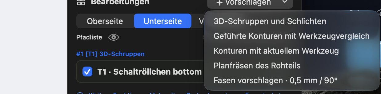
Automatic suggestions
Status: AVAILABLE
Use Suggest to have the program create suitable operations. The menu offers:
3D roughing and finishing – a complete workflow for 3D shapes with tool comparison (optionally including facing of the stock top, a remaining floor or roughing only).
Guided contours with tool comparison – outer and inner contours, optionally with a remaining floor, through-cutting and tabs.
Contours with the current tool.
Face the stock.
Suggest chamfers (e.g. 0.5 mm / 90°).
For recognized CAD features (holes, pockets, chamfers, fillets, thread core holes), additional suggestions are available directly on the selected geometry. The program compares up to three suitable tools, calculates every variant completely and shows the times. You can deliberately choose a slower variant as well.
Nothing is adopted without your confirmation. “Optimal” always means the best of the variants actually calculated – not a guarantee of the best possible solution worldwide.
Recalculate
Click Recalculate whenever you have changed something. The path list then shows movements and toolpath time. If a result is outdated, “Recalculate” appears in orange. Errors are explained briefly in your language.
Multi-sided and rotary-axis machining
Multiple sides (manual reclamping)
Status: AVAILABLE
Up to six sides, each with its own setup. In the CAM panel, switch using the side tabs (e.g. Top · Bottom · Front); the path list shows the time and movements for the selected side. The example in the main window shows a gear (“derailleur pulley”) with three setups. Export all sides using Export › Export all setups …. They are exported as one package with one file per side, zero points, tools, sequence and overview.
4th axis: indexing
Status: EXPERIMENTAL – virtually tested; output for Makera Z1 uses an independently implemented file postprocessor without manufacturer approval.
The workpiece is rotated to fixed angles using rotary axis A (e.g. 0°, 90°, 180°, 270°) and machined from above at each angle.
4th axis: radial rotary machining
Status: EXPERIMENTAL
Continuous rotation around the A axis with corresponding movement in Z – for round parts made from round bars. Roughing and finishing sequences with several tools, end supports, axial subregions and a material preview.
5 axes (A/C table)
Status: IN DEVELOPMENT – 3+2 indexing and simultaneous A/C finishing can only be planned virtually; real 5-axis output has not been approved.
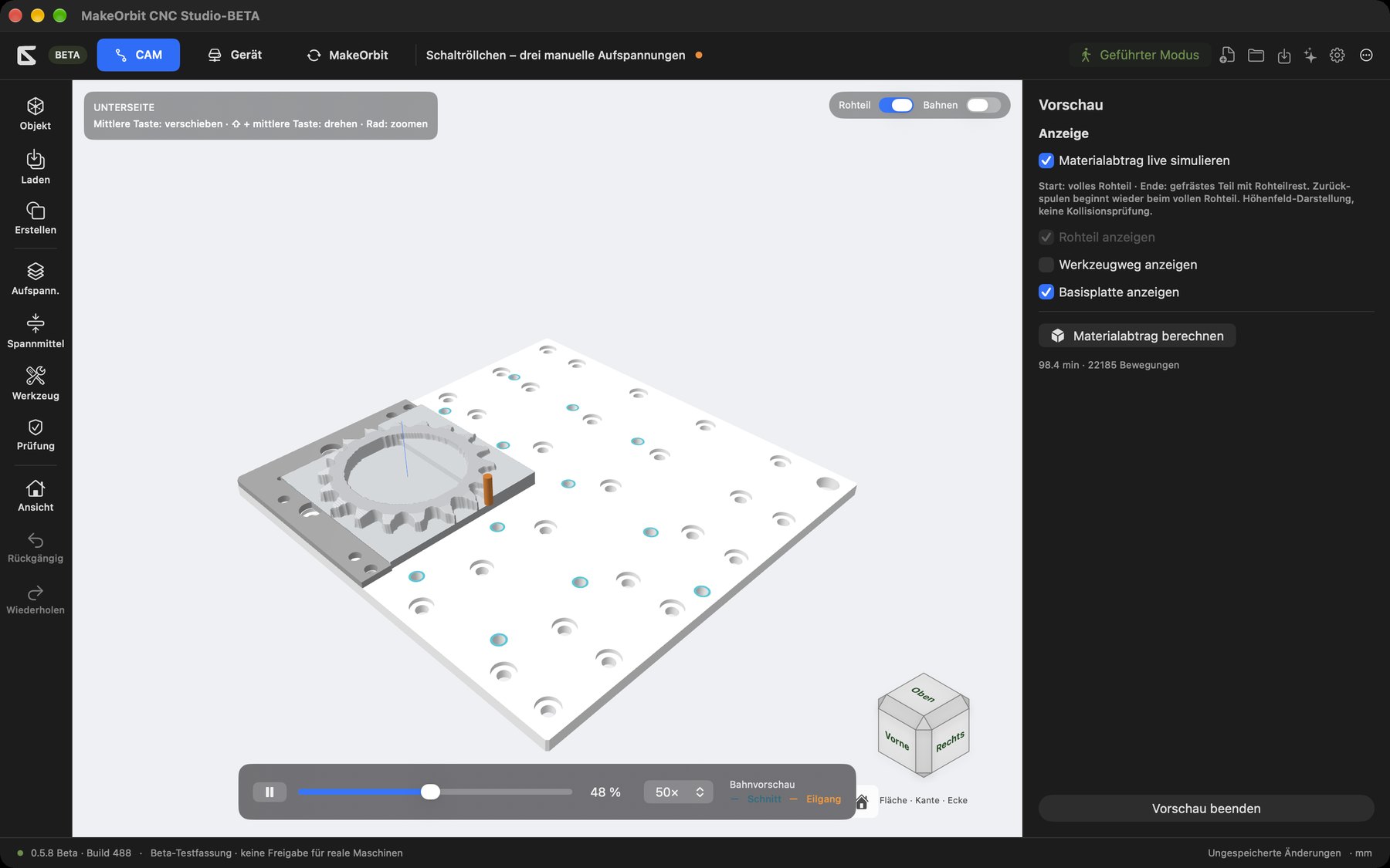
Preview and simulation
Status: AVAILABLE
Click Preview. The program switches to preview mode.
At the start, you see the full stock. Material is removed during playback; at the end, you see the milled part with the remaining stock. Rewinding starts again from the full stock.
Playback bar at the bottom: Start/Pause, time slider with percentage display, Speed 1×, 5×, 10×, 20×, 50×. The legend shows Cutting (turquoise) and Rapid (orange).
Select individual operations and play only those.
On the right under Display: Simulate material removal live, Show stock, Show toolpath (off by default in preview so the part remains clearly visible), Show base plate.
Calculate material removal – calculates the removed volume and compares it with the target model (Target comparison: remaining material and undersize are shown in color).
Toolpath time and number of movements.
Exit preview returns to the CAM view.
The preview is a visual representation. It does not replace a complete machine collision check.
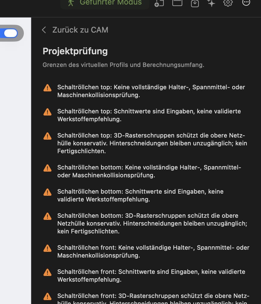
Project check
Status: AVAILABLE
Use Check on the left to see all notices, warnings and blocking conditions for your project: missing material values, fixture contacts, tool lengths, machine limits and outdated paths.
Contact and collision checking
Status: EXPERIMENTAL – tool, neck, holder and fixture contacts are checked; a complete machine collision check is IN DEVELOPMENT.
Create a machine file (export)
Status: AVAILABLE
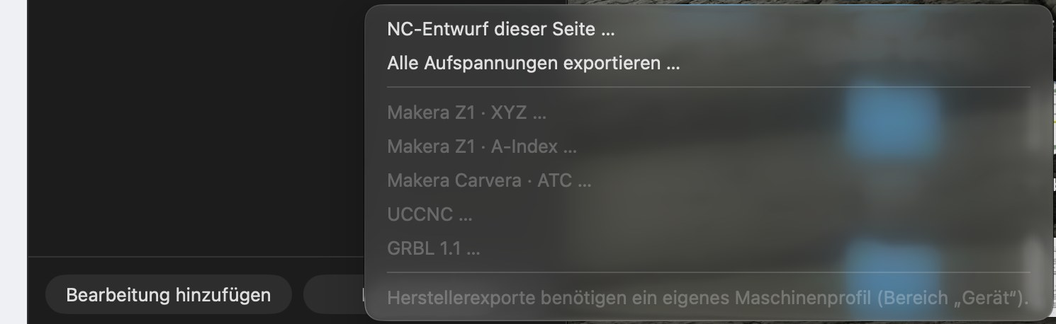
Click Export at the bottom and select the format. Only formats suitable for the machine are enabled.
Menu item
For
Status
NC draft of this side …
General checked machine file for the selected side
AVAILABLE
Export all setups …
Multi-sided package, one file per side
AVAILABLE
Makera Z1 · XYZ …
Makera Z1 / Z1 Pro
EXPERIMENTAL
Makera Z1 · A-Index …
Z1 with rotary module
EXPERIMENTAL
Makera Carvera · ATC …
Carvera with tool changer
EXPERIMENTAL
UCCNC …
e.g. STEPCRAFT
EXPERIMENTAL
GRBL 1.1 …
GRBL machines, e.g. TwoTrees
EXPERIMENTAL
LinuxCNC XYZAC (via More toolpath functions)
Custom 5-axis machines
EXPERIMENTAL
GRBL Laser (in the laser window)
Laser modules using GRBL
EXPERIMENTAL
Manufacturer-specific exports are enabled only once a custom machine profile has been configured in Device (menu notice: “Manufacturer-specific exports require a custom machine profile”).
Export control
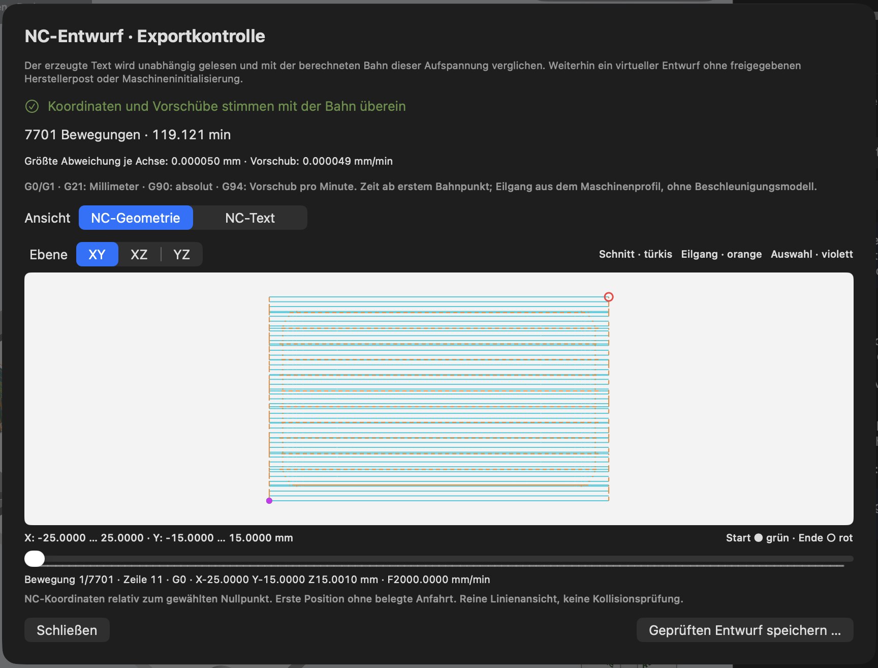
Before a file is saved, the NC draft · Export control window shows:
The result of the independent re-read verification: the generated text is read back in and compared with the calculated path – e.g. “Coordinates and feeds match the toolpath”, maximum deviation per axis 0.000050 mm.
Number of movements and toolpath time.
Commands used (e.g. G0/G1, G21 millimetres, G90 absolute, G94 feed per minute).
NC geometry view in the XY, XZ and YZ planes – only what is actually in the file is drawn (cutting turquoise, rapid orange, selection violet, start green, end red). Use the slider to select individual movements together with their line numbers.
NC text view – the complete file contents.
Save checked draft …, or saving the package for manufacturer-specific formats.
For manufacturer-specific formats, you also confirm the setup at the machine (e.g. workpiece zero set, tool clamped and measured). These confirmations apply only to this export and must be given again each time. An export package contains the NC file(s), an overview (HTML), a manifest with checksums and the complete project.
Important: The manufacturer-specific formats are independent implementations without manufacturer approval. Check every file before the first run on your machine – for example, with an air-cut test run at reduced speed.
Transfer the file to the machine
In the beta, you transfer the file yourself: using a USB stick, SD card or your machine manufacturer's software. Direct transfer from MakeOrbit CNC Studio is IN DEVELOPMENT (see Device).
Laser machining
Status: AVAILABLE (planning) · EXPERIMENTAL (laser file export for GRBL)
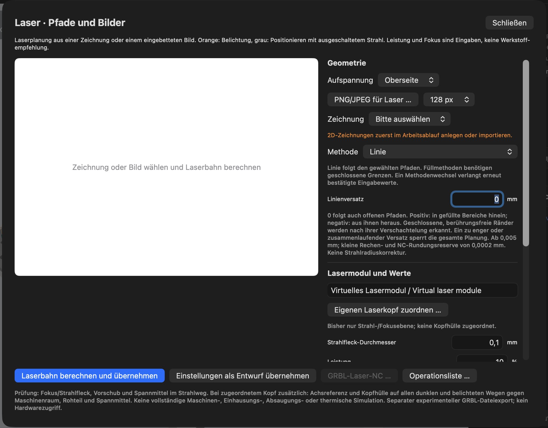
Open via Add operation › Laser · Paths and Images. In the Laser · Paths and Images window:
Geometry: select a setup, then either PNG/JPEG for laser … (with raster resolution, e.g. 128 px) or a drawing (import or create 2D drawings first).
Select a method (e.g. line, area fill, contour-parallel fill, image engraving) and set values such as line offset. Changing the method requires the values to be confirmed again.
Laser module and values: laser module, optionally Assign custom laser head …, spot diameter, power, feed, focus.
Calculate and adopt laser path, Adopt settings as a draft, GRBL laser NC … (file) or Operation list … (several laser steps).
In preview, orange means exposure and grey means positioning with the beam switched off. Power and focus are your inputs – not a material recommendation.
Vector lines: the laser follows drawing lines, including line offsets and outline open lines.
Area fill: raster (rows) or contour-parallel, with angle, spacing and edge inset; multiple areas, cut-outs and islands are recognized automatically.
Laser list: sort and activate several laser operations and plan them together; preview individually or as a complete list.
Laser head and focus: create custom laser heads with focal distance and offset and save them as templates.
Positioning moves always take place with the beam switched off. The program makes no statement about the effect on the material – test power and speed on scrap pieces.
Device: machines, connections and monitoring
Click Device in the top bar.
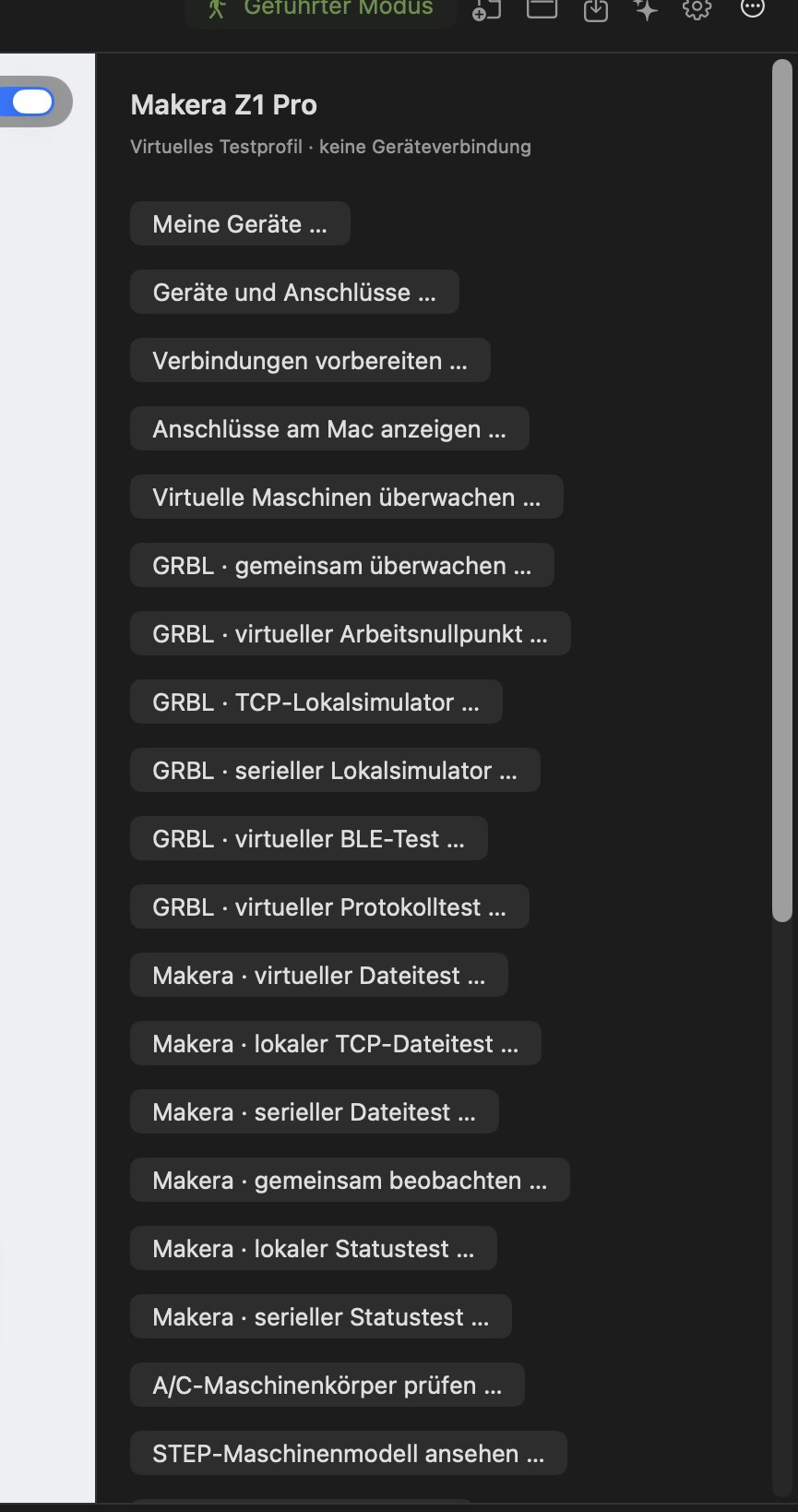
At the top, this area shows the active machine profile (e.g. “Makera Z1 Pro · Virtual test profile · no device connection”), followed by these functions:
Button
Purpose
Status
My devices …
Create records for your own real devices (manufacturer, model, name)
EXPERIMENTAL
Devices and ports …
Link devices with ports and a profile
EXPERIMENTAL
Prepare connections …
Prepare connection details (USB/serial, network, Bluetooth) without connecting
EXPERIMENTAL
Show ports on this Mac …
Read detected serial/USB ports only
AVAILABLE
Monitor virtual machines …
Observe the built-in simulators together
EXPERIMENTAL
GRBL · … / Makera · … (virtual tests)
Test connection, file, status and zero point on simulated machines
EXPERIMENTAL
Check A/C machine bodies …
Virtual collision checking of machine parts
IN DEVELOPMENT
View STEP machine model …
View a 3D model of a machine as a reference
EXPERIMENTAL
Machine profiles
Status: AVAILABLE
In addition to the supplied profiles (Makera, STEPCRAFT, TwoTrees), you can create your own machines with working space, spindle-speed and feed limits. Profiles can be exported, imported and archived.
Your own devices and ports
Status: EXPERIMENTAL
You can create records for your real devices with manufacturer, model and display name and assign them to local connections (USB/serial, network/TCP, Bluetooth). Bluetooth device discovery is passive – nothing is connected.
Connect, monitor, control
Status: IN DEVELOPMENT – in the beta, usable only with the built-in virtual machines (simulators).
Planned and checked on virtual machines:
Monitor several machines simultaneously; control only the selected one.
Connecting, transferring a file and starting are three separate steps – connecting never starts a job.
Status display (idle, running, paused, alarm, positions).
Manual incremental movements (jog) only within confirmed limits.
Read and set the workpiece zero with read-back verification.
Safety principle: the program never initiates a movement, a spindle or a laser by itself. You deliberately trigger every real action yourself.
MakeOrbit connection
Status: AVAILABLE (Mac, with the installed and licensed 645DFMakeOrbit app)
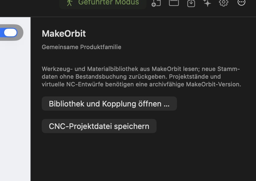
645DFMakeOrbit is the management app in the MakeOrbit family. Together with CNC Studio:
Tools and materials are read from MakeOrbit. MakeOrbit is the authoritative source: you maintain existing records in MakeOrbit.
New cutters and material sizes that you create in CNC Studio are transferred automatically to MakeOrbit (without an inventory booking).
Projects and machine files are automatically archived in the associated MakeOrbit project – including the calculated machining time. From MakeOrbit, you can open an archive directly in CNC Studio again.
The MakeOrbit area offers two buttons: Open library and pairing … and Save CNC project file. You can also find the tool and material library from MakeOrbit in the MakeOrbit tab of the tool library.
Set up pairing:
Enable CNC sharing in MakeOrbit and copy the pairing key.
In CNC Studio, select MakeOrbit › Open library and pairing … and paste the key into the secure field.
The key is stored in macOS Keychain. The apps then synchronize automatically approximately every minute.
The connection runs only locally on your Mac – no Internet or network access. Never share the pairing key.
Windows integration will follow with MakeOrbit for Windows (IN DEVELOPMENT).
AI planning assistant (optional)
Status: EXPERIMENTAL – optional, not required.
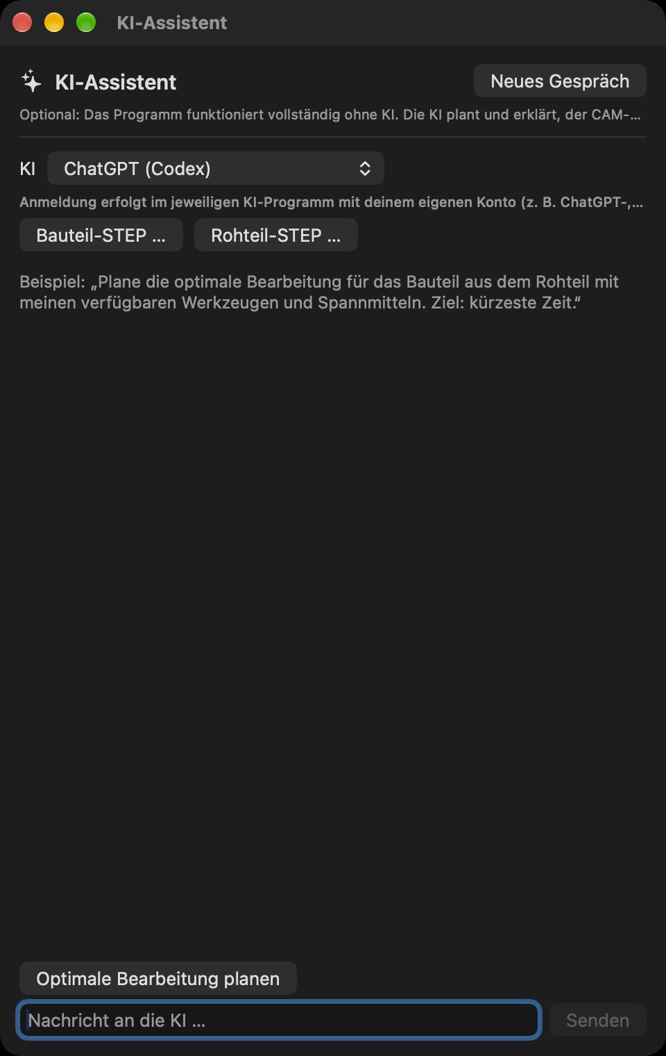
Open it with ⌥⌘K or the sparkle icon at the top. The assistant can work with your own account for ChatGPT (Codex), Claude (Claude Code), Gemini, or with a Claude API key.
Using the AI Assistant window:
Under AI, select the provider (e.g. “ChatGPT (Codex)”). Sign in through the respective AI application using your own account; if you are not signed in, the window displays a sign-in button.
Optionally select Part STEP … and Stock STEP … (for the stock, the enclosing rectangular block is used).
Click Plan optimal machining or write your own message, e.g. “Plan the optimal machining process for the part from the stock using my available tools and fixtures. Goal: shortest time.”
New conversation starts again from the beginning.
How it works:
The AI plans and explains; the application calculates and checks. The AI does not generate its own toolpaths or G-code.
It uses only cutters that you have confirmed as available, and the fixtures you have entered.
Candidates (K1, K2 …) are fully calculated and compared by time, tool changes and remaining material. You can view a candidate in the workspace.
A candidate is adopted only after your confirmation in the normal confirmation dialog.
Privacy: Dimensions, recognized features, tool data and metrics are transmitted – not CAD files. Before first use, you confirm a notice. Your AI account's terms apply (including possible costs and usage limits).
Without an AI account, during an outage or when your usage limit is reached, you can continue working manually as usual.
Save and open projects
Status: AVAILABLE
Save: ⌘S. Save As …: ⇧⌘S. Open: ⌘O.
File extension: .mocnc. Contents: model (original and geometry), placement, stock, setups, machine, tool and material data, and the calculated results.
When opened, the file is checked and saved paths are independently recalculated. Outdated previews are discarded and reported; your inputs are preserved.
Project files contain no license, keys or connection data – nevertheless, before sharing them, check whether the models and project data contain confidential information.
Undo/Redo: up to 20 steps.
If another application has modified the file, it is not silently overwritten.
Settings
Status: AVAILABLE
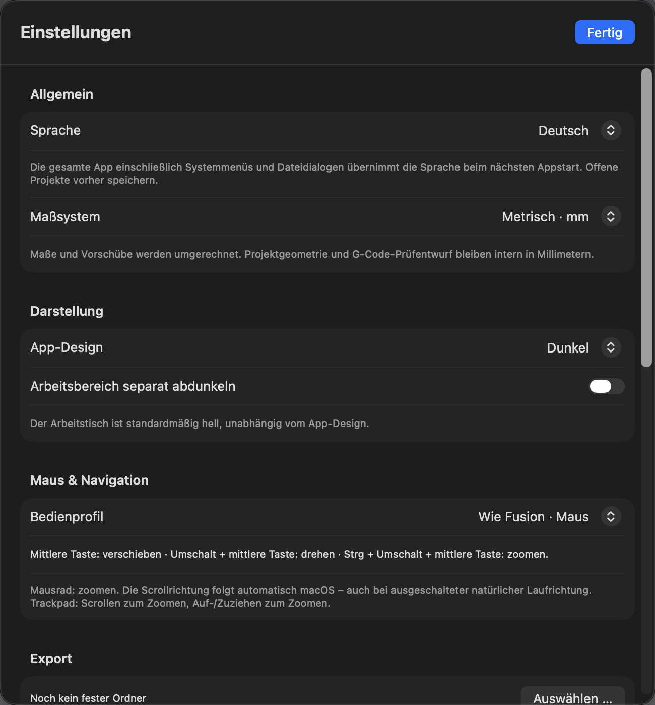
Open Settings using the gear icon at the top right; Done closes the settings.
Section
Setting
Explanation
General
Language
German or English. The entire app, including system menus and file dialogs, adopts the language at the next start. Save open projects first.
General
Measurement system
Metric (mm) or inches. Dimensions and feeds are converted; project geometry and machine files remain internally in millimetres. Values are always saved exactly.
Appearance
App theme
E.g. Dark or Light.
Appearance
Darken workspace separately
The worktable is light by default, independently of the app theme.
Choose … sets the folder in which the export dialog starts.
License
Status, devices, slots, computers
License status and validity period; My devices …, Devices and connections …, Manage machine slots …, Manage computers … (IN DEVELOPMENT – the production licensing service is not yet connected).
Version & Updates
Check for updates
Version display; update service IN DEVELOPMENT.
Safety
Please read this section before milling for the first time.
The beta does not control a real machine. You initiate everything that happens at the machine yourself.
Check every machine file before the first run (air-cut trial run, reduced feed, emergency stop within reach).
Measure the stock and tool length.
Wear safety glasses, use extraction, and never reach into a running machine.
For laser work: approved protective eyewear, fire precautions, and never leave it unattended.
The preview is a visualization, not complete proof of collision avoidance.
Catalog cutting values are starting values. The material, machine and workholding influence the result.
Feature overview and development status
Area
Feature
Status
Operation
German/English, settings, view cube, Undo
AVAILABLE
Operation
Guided Mode
AVAILABLE
Operation
Guided DXF/SVG and automatic rest roughing
EXPERIMENTAL
Operation
Setup assistant with material catalog
AVAILABLE
Import
STEP, STL, 3MF, DXF, SVG, image
AVAILABLE
Import
Fusion 360 add-in
AVAILABLE
Import
SolidCraft directly into CNC Studio
IN DEVELOPMENT
Import
Relief from images
IN DEVELOPMENT
Part
Placement, copies, fill stock
AVAILABLE
Part
Multiple different parts
IN DEVELOPMENT
2D CAM
Facing, contour, pocket, drilling, hole milling
AVAILABLE
2D CAM
Internal and external threads
AVAILABLE
3D CAM
Roughing, finishing, chamfers, fillets
AVAILABLE
3D CAM
Remaining material with follow-up cutters
EXPERIMENTAL
Multi-axis
Multiple sides with manual reclamping
AVAILABLE
Multi-axis
Indexed and radial 4th axis
EXPERIMENTAL
Multi-axis
5 axes A/C
IN DEVELOPMENT
Simulation
Preview with material removal, target comparison
AVAILABLE
Simulation
Complete machine collision checking
IN DEVELOPMENT
Export
NC draft with independent re-read check
AVAILABLE
Export
Makera, GRBL, UCCNC and LinuxCNC files
EXPERIMENTAL
Laser
Vector, fill, image, list
AVAILABLE
Laser
GRBL laser file export
EXPERIMENTAL
Device
Profiles, own devices, connections
EXPERIMENTAL
Device
Real connection, transfer and control
IN DEVELOPMENT
MakeOrbit
Pairing, master data, archive
AVAILABLE
AI
AI planning assistant
EXPERIMENTAL
License
Trial period, purchase, online activation
IN DEVELOPMENT
Platform
Windows version
IN DEVELOPMENT
Platform
Mac App Store
IN DEVELOPMENT
Keyboard shortcuts
Shortcut
Function
⌘N
New project (setup assistant)
⌘O
Open project
⌘S
Save
⇧⌘S
Save As
⌘Z / ⇧⌘Z
Undo / Redo
⇧⌘G
Guided Mode
⌥⌘K
AI assistant
⌥ while dragging
Move without snapping
⌘- or ⇧-click
Select multiple parts
Esc
Cancel numeric input
Frequently asked questions
Do I need prior knowledge? No. Start with Guided Mode.
Can I use the application without the Internet? Local planning is intended to work without an AI account. The described offline trial period and license activation belong to the planned licensing model; purchase and activation have not yet been enabled.
Why is my milling time so long? The catalog values are conservative. Allow larger shank diameters in Guided Mode, or adjust stepdown and stepover in expert mode.
Why is “Recalculate” orange? You have changed something. The old path is no longer appropriate and must be recalculated.
Why is my calculation blocked? The application has found a problem, e.g. a tool that is too short, fixture contact, or a part outside the stock. The message states the cause and solution.
Can I send directly to my machine? Not yet in the beta. Export the file and transfer it using USB, an SD card or the manufacturer's software.
Is my file sent to the AI? No, only dimensions and metrics – and only when you actively use the AI assistant.
Can I share projects? Yes. A .mocnc file contains everything needed, but no license or connection data.
Glossary
Term
Explanation
Allowance
Material deliberately left during roughing and removed during finishing
Setup
Position and securing of the stock for one machining side
Stepover
Distance between two neighbouring toolpaths
Part
The finished part to be produced
CAM
Computer-Aided Manufacturing: planning manufacturing on a computer
CAD
Computer-Aided Design: designing on a computer
Spindle speed
Revolutions of the cutter per minute
Rapid move
Fast movement without cutting
Chamfer
Bevelled edge
G-code / NC file
List of commands for the machine
Tab
Small material bridge that holds a cut-out part in place
Island
Area left standing inside a pocket
Ball-nose cutter
Cutter with a rounded tip for 3D surfaces
Zero point
Reference point for all coordinates
Spoilboard
Backing that protects the table when cutting through
Postprocessor
Translates toolpaths into the dialect of a machine controller
Stock
The unmachined piece of material
Flat end mill
Cutter with a flat end face; the all-rounder
Finishing
Fine final machining
Roughing
Coarse, rapid removal of material
Fixtures
Clamps and jaws that hold the stock
Collet
Holder for the cutter shank
STEP
CAD file format with exact geometry
STL / 3MF
File formats made up of triangle meshes
Pocket
Cleared recess
Feed
Speed of the cutter through the material
Tool number (T1, T2 …)
Slot or identifier of the tool in the program
Stepdown
Plunge depth per pass
Contact and further information
Website: 645df.de · Contact: hello@645df.de. The public beta test has not yet started.
Beta feedback: Please note the step, file, language, unit, expected result, actual result and, if possible, include a screenshot.
Note: Makera, Carvera, STEPCRAFT, TwoTrees, Fusion 360, SolidCraft, ChatGPT, Claude and Gemini are trademarks of their respective owners. MakeOrbit CNC Studio is an independent product and is not affiliated with these manufacturers.