
An operation is a machining step using one tool, e.g. “Outside contour with a 3-mm end mill”. Click Add operation at the bottom.
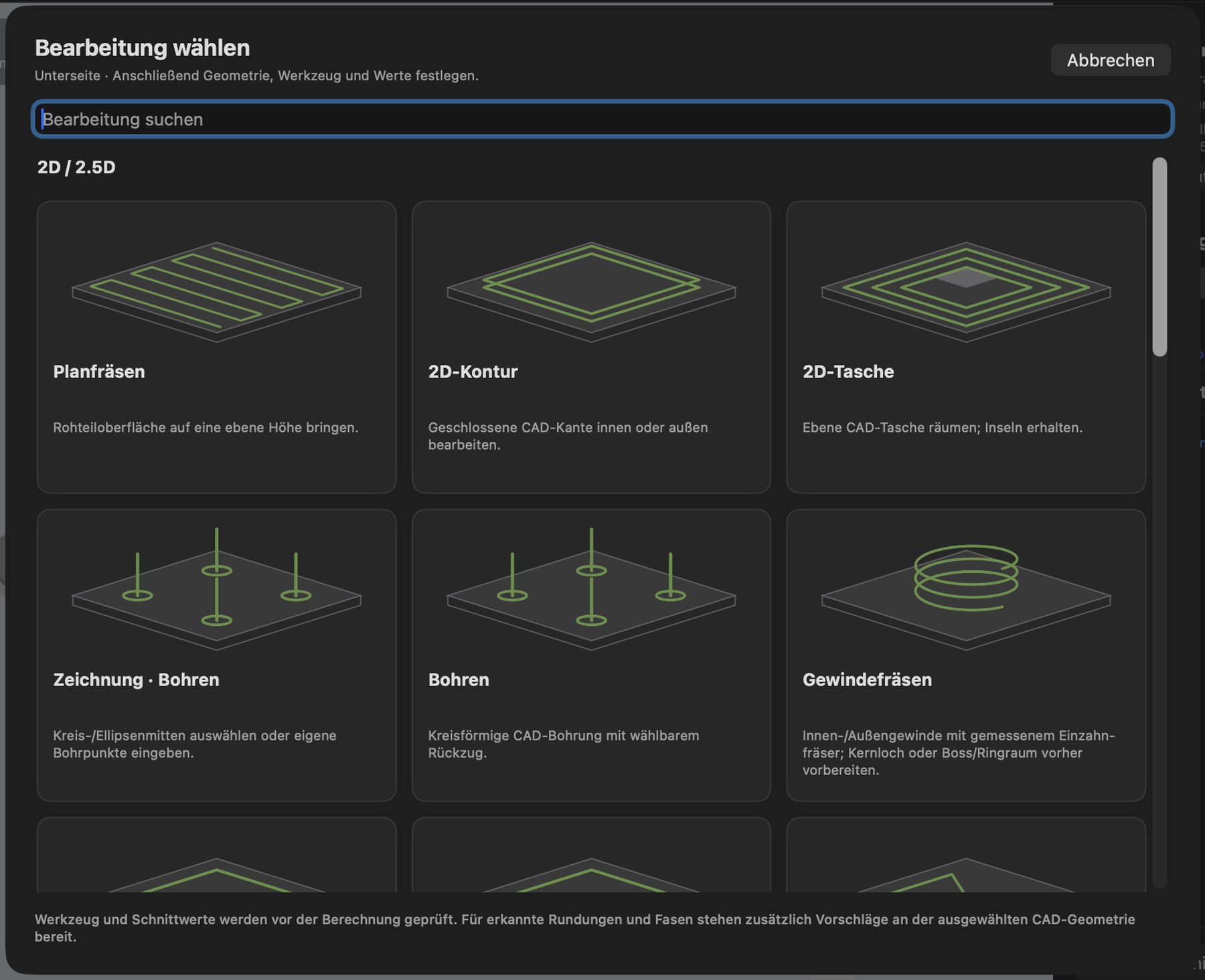
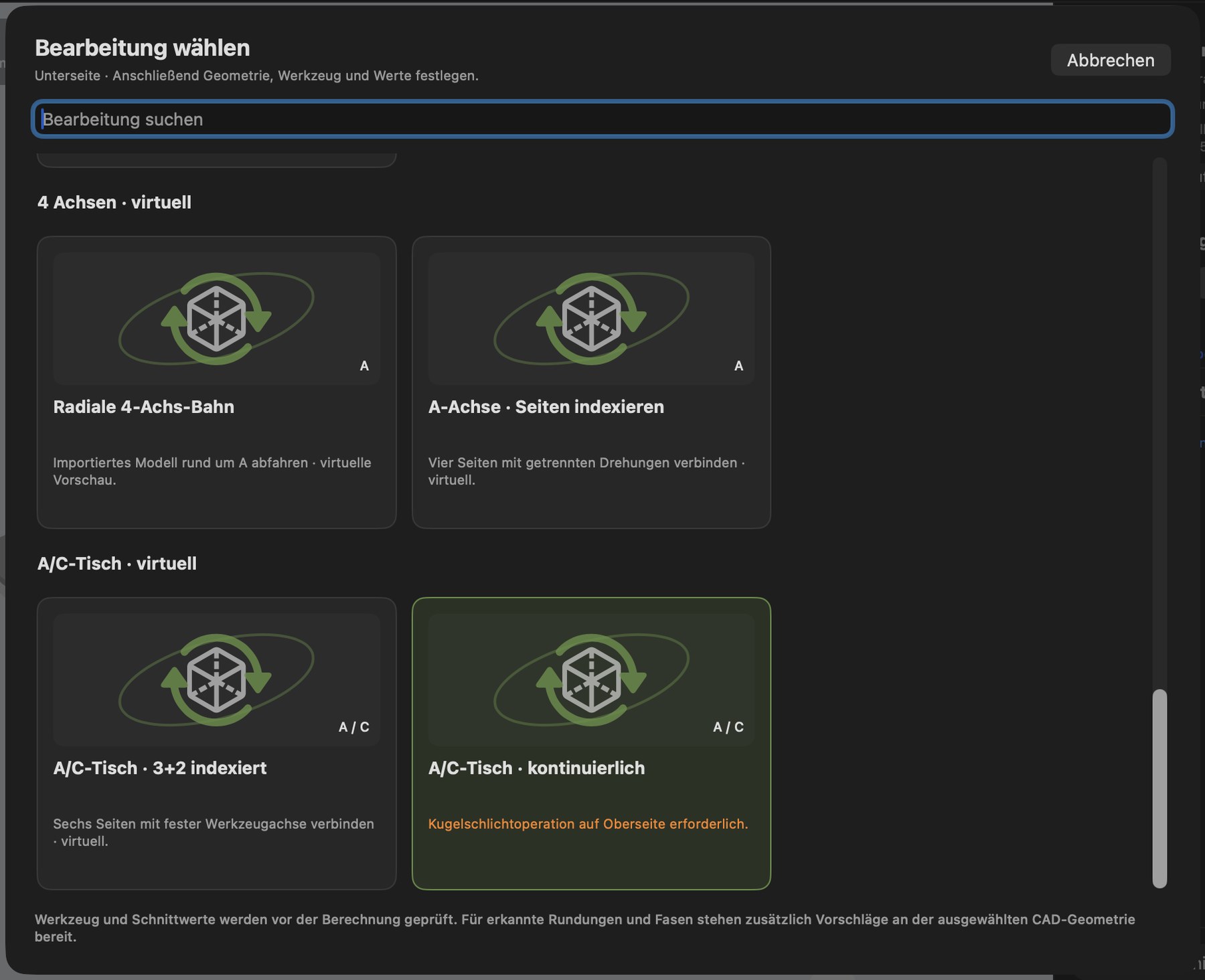
The Choose operation window always applies to the currently selected side. It has a search field and is organized into groups; each card has an image and a short explanation. Strategies whose prerequisites are missing are displayed but disabled, with the reason shown in orange (e.g. “First create a closed drawing in this setup”).
| Group | Operation | Short description in the app |
|---|---|---|
| 2D / 2.5D | Facing | Bring the stock surface to a flat height |
| 2D / 2.5D | 2D contour | Machine a closed CAD edge on the inside or outside |
| 2D / 2.5D | 2D pocket | Clear a flat CAD pocket; preserve islands |
| 2D / 2.5D | Drawing · Drilling | Select circle/ellipse centers or enter your own drilling points |
| 2D / 2.5D | Drilling | Circular CAD hole with selectable retract |
| 2D / 2.5D | Thread milling | Internal/external threads using a measured single-tooth cutter |
| 2D / 2.5D | Edge chamfer | Machine a planar chain of edges with a chamfer cutter |
| 2D / 2.5D | Drawing · Chamfer | Chamfer along a closed drawing |
| 2D / 2.5D | Trace lines | Follow open or closed drawing paths |
| 2D / 2.5D | Drawing · Contour | Mill a closed drawing with cutter compensation |
| 2D / 2.5D | Drawing · Pocket | Clear a drawn area; leave inner contours uncut |
| 3D | 3D raster roughing | Remove bulk material layer by layer |
| 3D | 3D contour finishing | Finish flat steps and walls with a flat cutter |
| 3D | 3D ball-nose finishing | Smooth 3D surfaces with a ball-nose cutter |
| Laser | Laser · Paths and Images | Laser lines, area fill and image engraving |
| 4 axes · virtual | Radial 4-axis path | Follow an imported model around A |
| 4 axes · virtual | A axis · Index sides | Connect four sides with separate rotations |
| A/C table · virtual | A/C table · 3+2 indexed | Connect six sides with a fixed tool axis |
| A/C table · virtual | A/C table · Continuous | Ball-nose finishing with simultaneous A/C rotation |
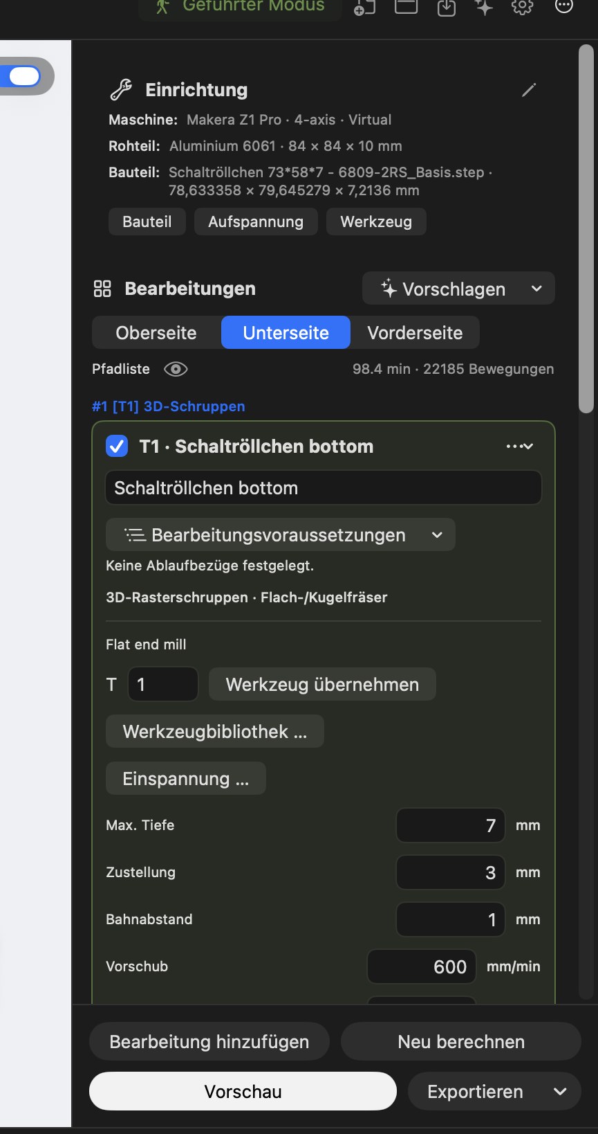
Each operation appears as a card, e.g. “#1 [T1] 3D roughing”. Click the card to expand it:
- Name of the operation (freely editable).
- Operation prerequisites – which earlier operations are needed (e.g. “rough first, then finish”).
- Strategy and tool type (e.g. “3D raster roughing · Flat/ball-nose cutter”).
- Tool: tool number (T), Use tool, Tool library … and Tool holding … (stick-out and holder).
- Values: e.g. maximum depth, stepdown, stepover, feed, plunge feed, spindle speed, allowances and strategy-specific options.
Use the checkbox to temporarily disable an operation, or the “…” menu to duplicate it, change its position in the sequence or delete it. Numeric fields apply your value only when you leave the field; Esc cancels an entry. Unchanged values do not trigger recalculation.
Facing
Status: AVAILABLE
Mills the top of the stock flat. Zigzag or one-way paths, X/Y direction or automatic selection by shortest time. Entry and exit take place outside the stock.
2D contour
Status: AVAILABLE
Mills along a line – inside, outside or on the line. Options:
- Stepdown: in steps, as a ramp (sloping entry) or as a spiral.
- Tabs: rectangular or triangular, automatically distributed, at your own positions or placed graphically (with the mouse in a zoomable top view).
- Custom start point: selectable graphically on the contour.
- Remaining floor or cut through to the bottom of the stock.
- Allowance and finishing pass.
- Contours from STEP edges, complete STEP body outlines or 2D drawings.
Status: AVAILABLE
Clears a closed area – including areas with islands left standing. Paths can follow contours or run parallel at a freely chosen angle. Recognized CAD pockets (rectangular, polygonal, with circular walls, elliptical, concave) are taken over with their actual floor depth. Optional: roughing allowance with separate wall and floor finishing, rest material with a smaller follow-up cutter, and comparison of several tool sequences by time and remaining material.
Drilling and hole milling
Status: AVAILABLE
- Drilling: simple holes, chip breaking, deep-hole drilling with partial or full retract, uniform stepdowns. Holes from STEP (six directions) or drawing centers. The sequence can be optimized for time.
- Hole milling: mill larger holes in a circular motion using a smaller end mill.
Thread milling
Status: AVAILABLE
Internal and external threads using a single-tooth thread mill. The tooth geometry is taken from your measurements; core holes and bosses can be taken from STEP. Before calculation, you confirm that the core hole or boss is prepared. No certification of a standard or fit is provided.
Chamfers and fillets
Status: AVAILABLE
Existing chamfers and fillets are recognized from STEP and suggested; you confirm the tool and operation. You can also create chamfers on arbitrary edges or 2D drawings.
3D roughing
Status: AVAILABLE
Removes bulk material from 3D shapes using an end mill, layer by layer. Options: raster angle, stepover, separate side and floor allowances, a limited working area, surface selection, clearance from preceding operations (skip areas already cleared, using the combined cleared areas of earlier flat end mill paths when the option is enabled anew), and comparison of different path variants.
3D finishing
Status: AVAILABLE
Produces a smooth surface: raster with a ball-nose cutter, height contours for steep walls, contour finishing with a flat cutter for flat steps. Options: tolerance, scallop height, surface selection, point reduction.
Automatic suggestions
Status: AVAILABLE
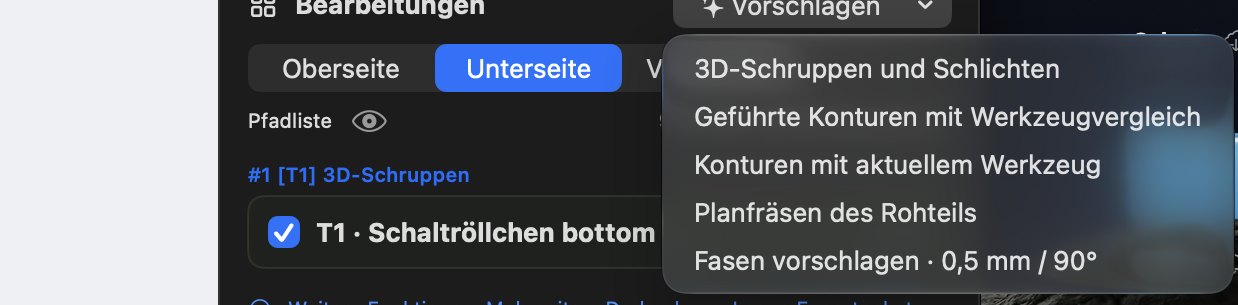
Use Suggest to have the program create suitable operations. The menu offers:
- 3D roughing and finishing – a complete workflow for 3D shapes with tool comparison (optionally including facing of the stock top, a remaining floor or roughing only).
- Guided contours with tool comparison – outer and inner contours, optionally with a remaining floor, through-cutting and tabs.
- Contours with the current tool.
- Face the stock.
- Suggest chamfers (e.g. 0.5 mm / 90°).
For recognized CAD features (holes, pockets, chamfers, fillets, thread core holes), additional suggestions are available directly on the selected geometry. The program compares up to three suitable tools, calculates every variant completely and shows the times. You can deliberately choose a slower variant as well.
 Nothing is adopted without your confirmation. “Optimal” always means the best of the variants actually calculated – not a guarantee of the best possible solution worldwide.
Recalculate
Click Recalculate whenever you have changed something. The path list then shows movements and toolpath time. If a result is outdated, “Recalculate” appears in orange. Errors are explained briefly in your language.